2 layers245.1 × 160 mm
8-Bit CPU 32k
slu4coder/Minimal-64x4-Home-Computer
My DIY TTL home computer with VGA and PS/2 and 4x the processing power of a Commodore C64 or Apple II.
139 parts326

 sky-dragn/6502fb1
A framebuffer for the 6502, implemented in discrete logic
6502fb is an open-source printed circuit board by sky-dragn, from the sky-dragn/6502fb repository on GitHub. It is a 4-layer board of 140 × 110 mm with 114 parts on 225 nets, routed with 2,228 tracks and 637 vias.
It is built around the 74AHC30D, 74LV08PW and 74AC109PC, with the 74HC00D, 74LV04D and 74LV32DB among its other parts. Its parts include 37 capacitors, 34 ICs, 21 connectors, 11 resistors and 1 crystal.


A 160 by 120 pixel, 256-color framebuffer and VGA generator for a 6502-based computer, made for CMU 98-341 Build Your Own Breadboard Computer.
Heavily inspired by Ben Eater's "world's worst video card" saga, but with many improvements:
This repo contains the KiCad files for the board, a corresponding Verilog design and testbench, and a software simulator.
The board went through 2 revisions before it worked fully:
Revision 1 worked well enough to generate a valid VGA signal, but I made a major mistake on the SRAM pinout which led to it not being able to interface with the 6502 computer. Another mistake: my minimum via diameter was too small, so it cost like $40 extra...
However, despite these faults, I was able to bodge the row and column pins to allow it to display an image from an EEPROM.
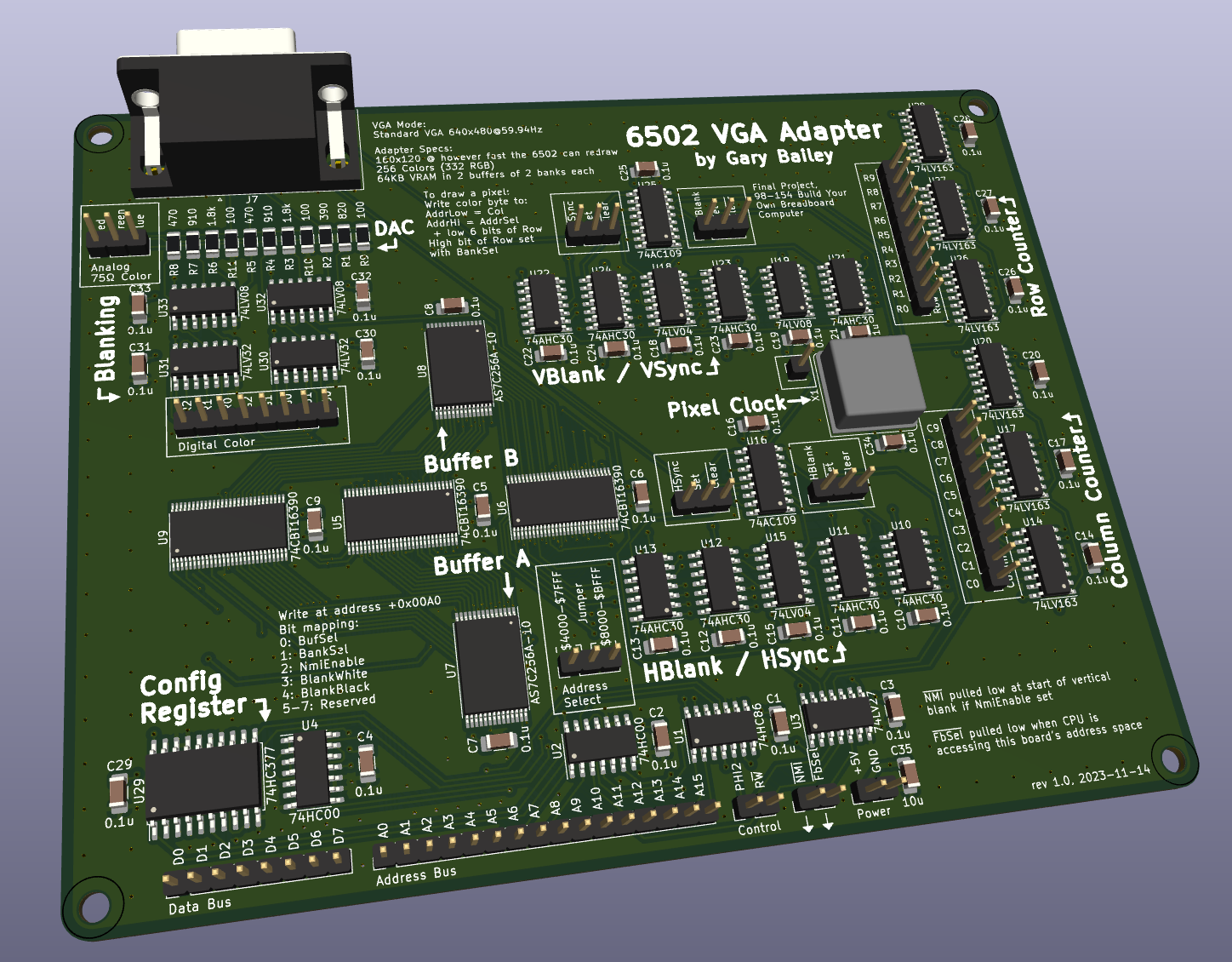 KiCad render
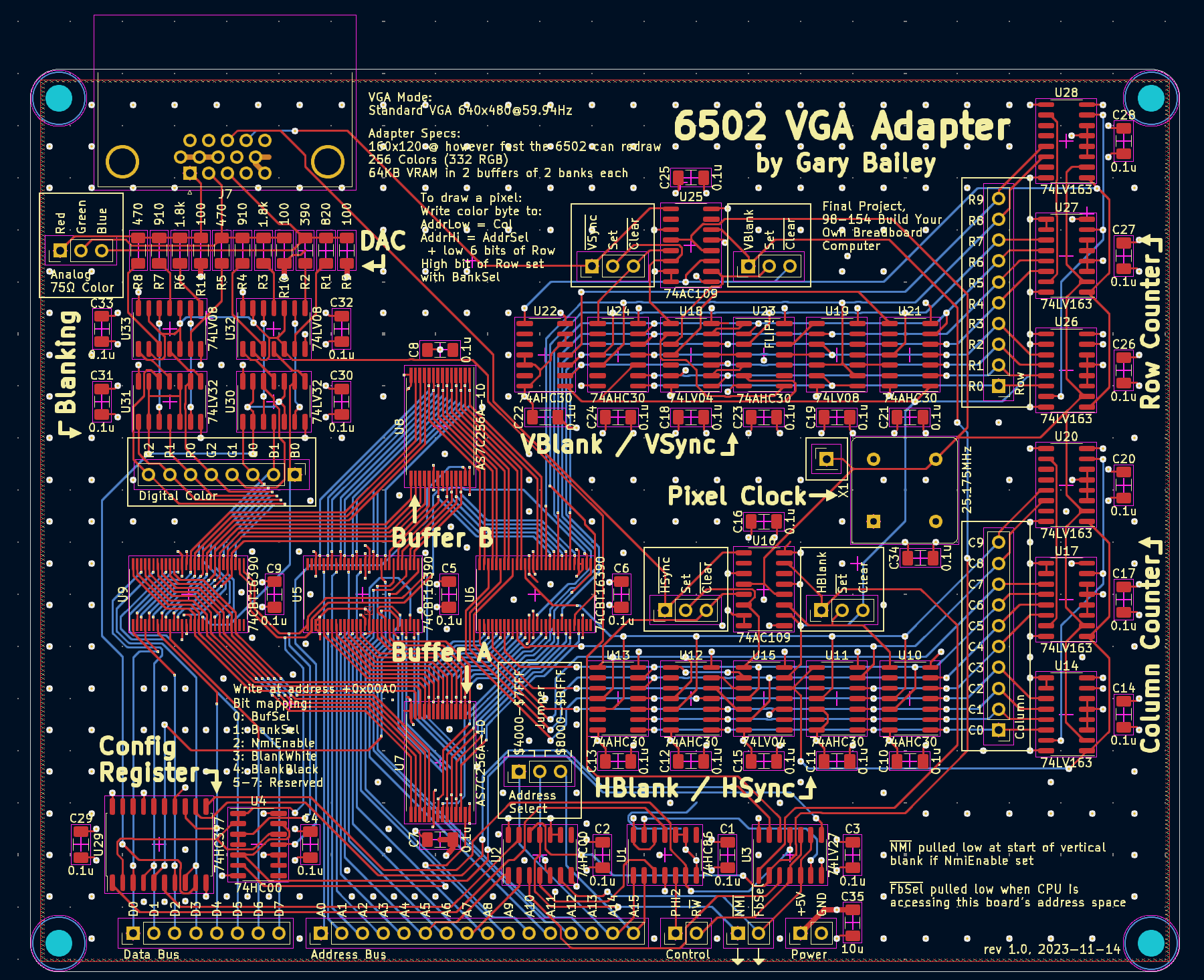 KiCad board view
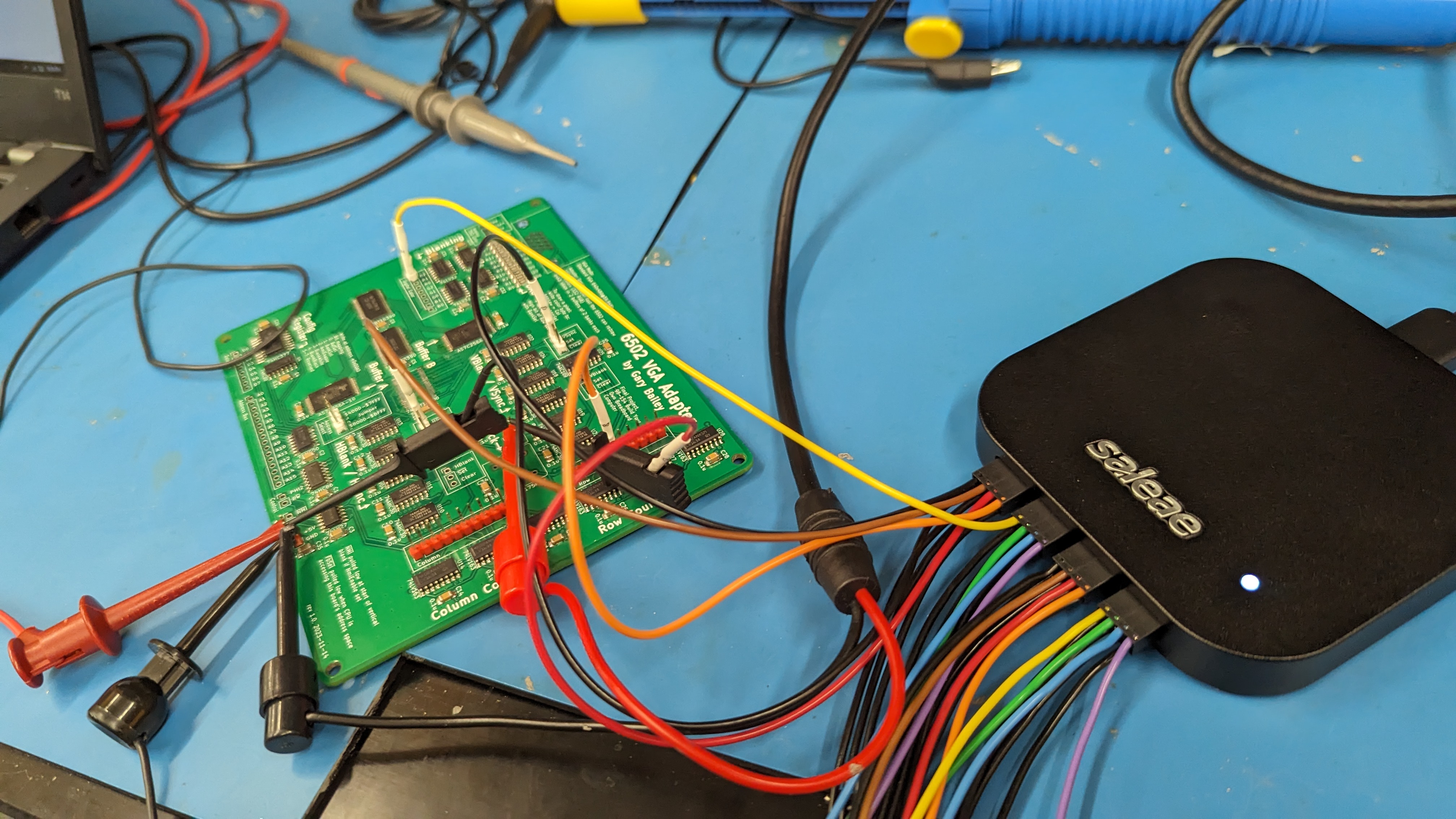 Part of the arduous debugging
process that eventually led to me discovering the SRAM mistake...
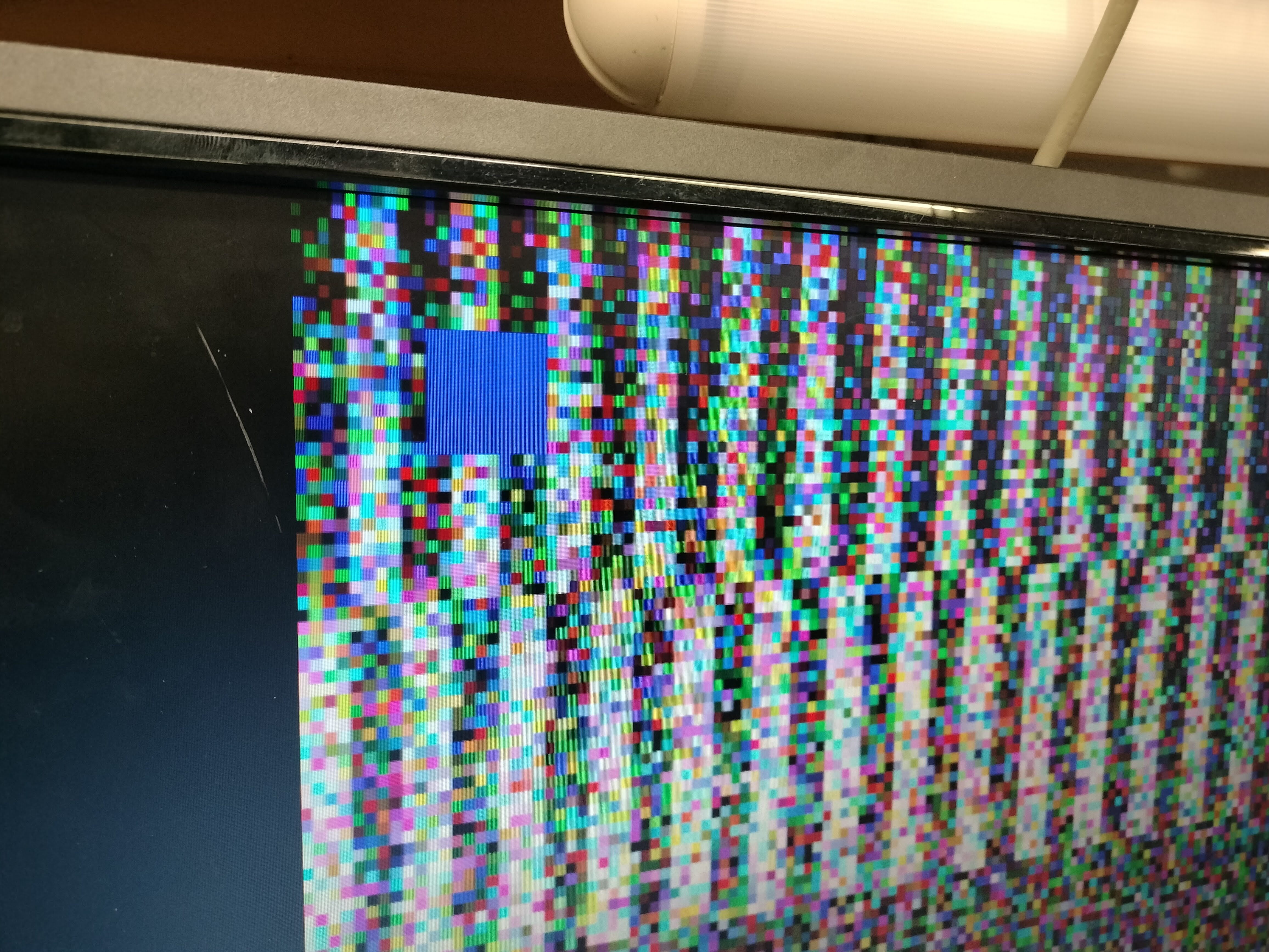
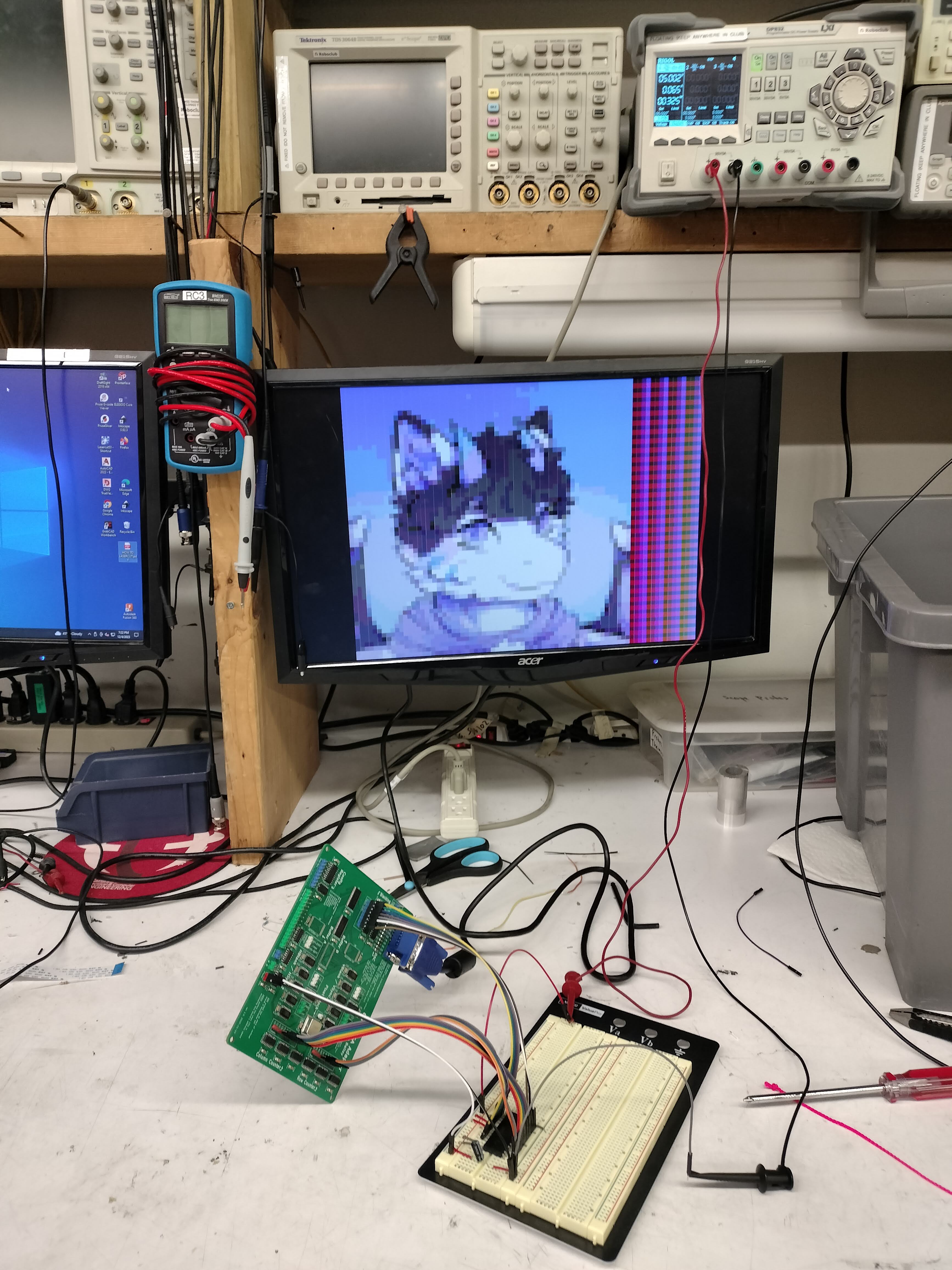 It works! (with a static image...) The
EEPROM I used here has a much slower read speed than the SRAMs I designed for,
which leads to the vertial artifacts on some pixels here.
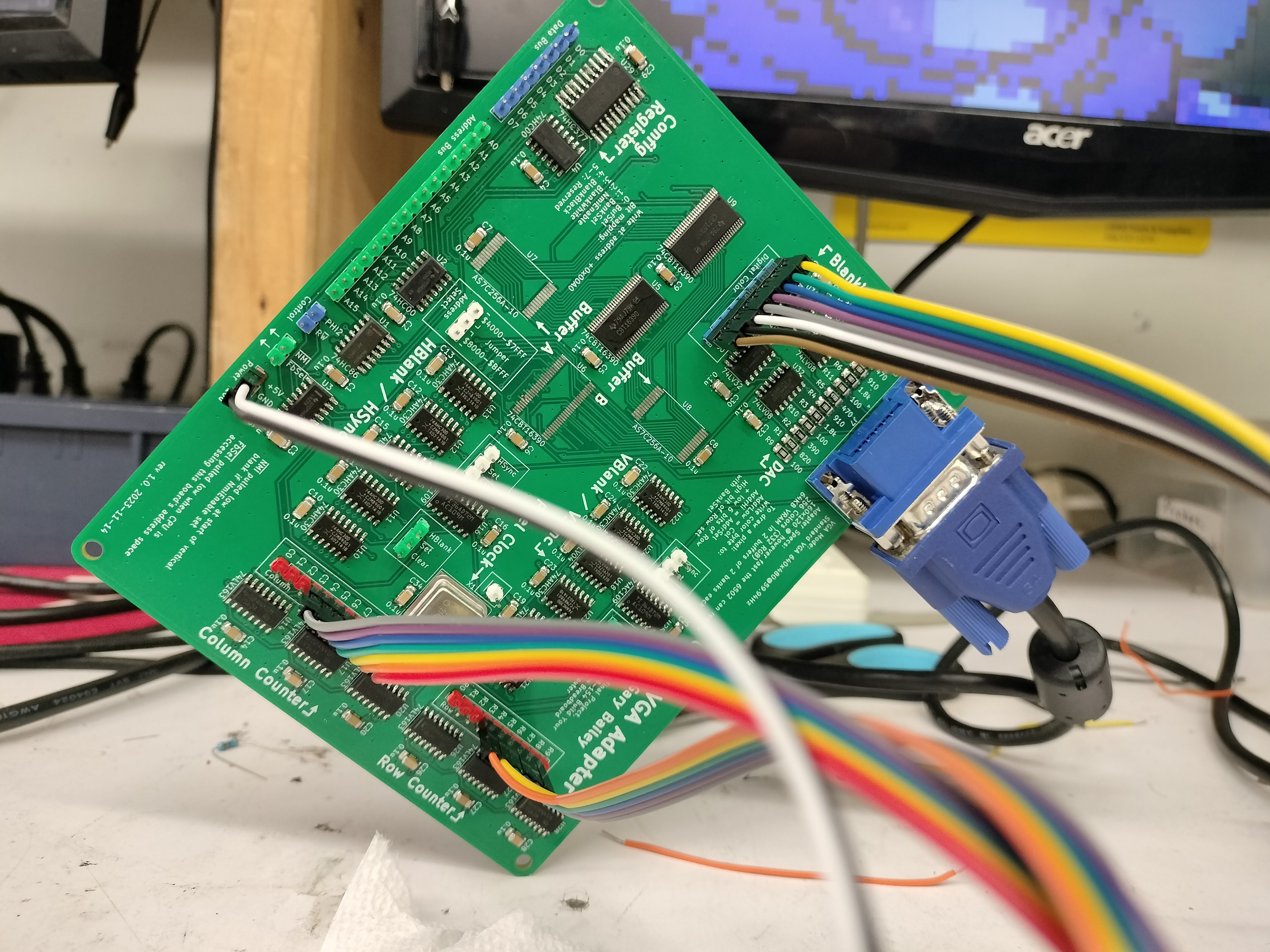 Closeup of Rev1 bodges: SRAMs removed and row/column signals routed to EEPROM + color routed in through header
Revision 2 fixed the pinout of the SRAM ICs, fixed the via size issue, added a debug header for the config register, and added an optional 5V regulator that can be used to power the entire computer.
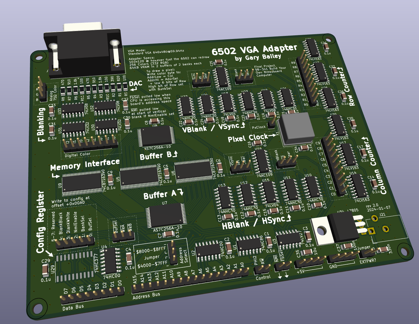 KiCad render
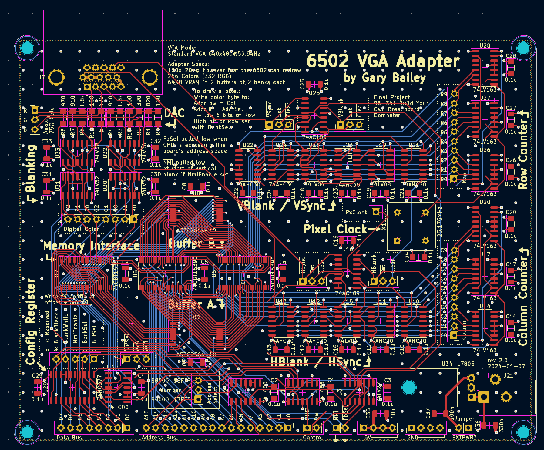 KiCad board view
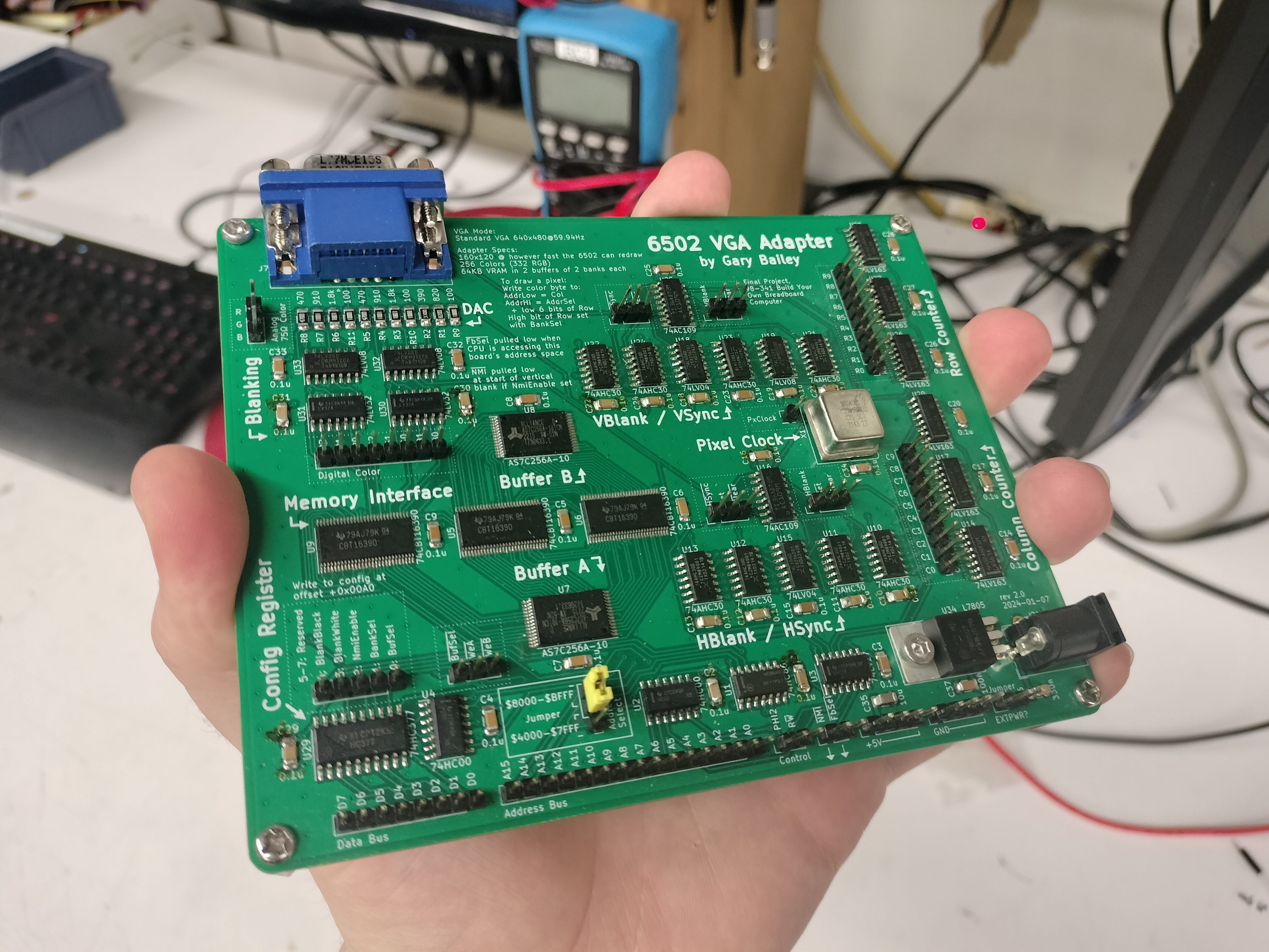 Final assembled board!
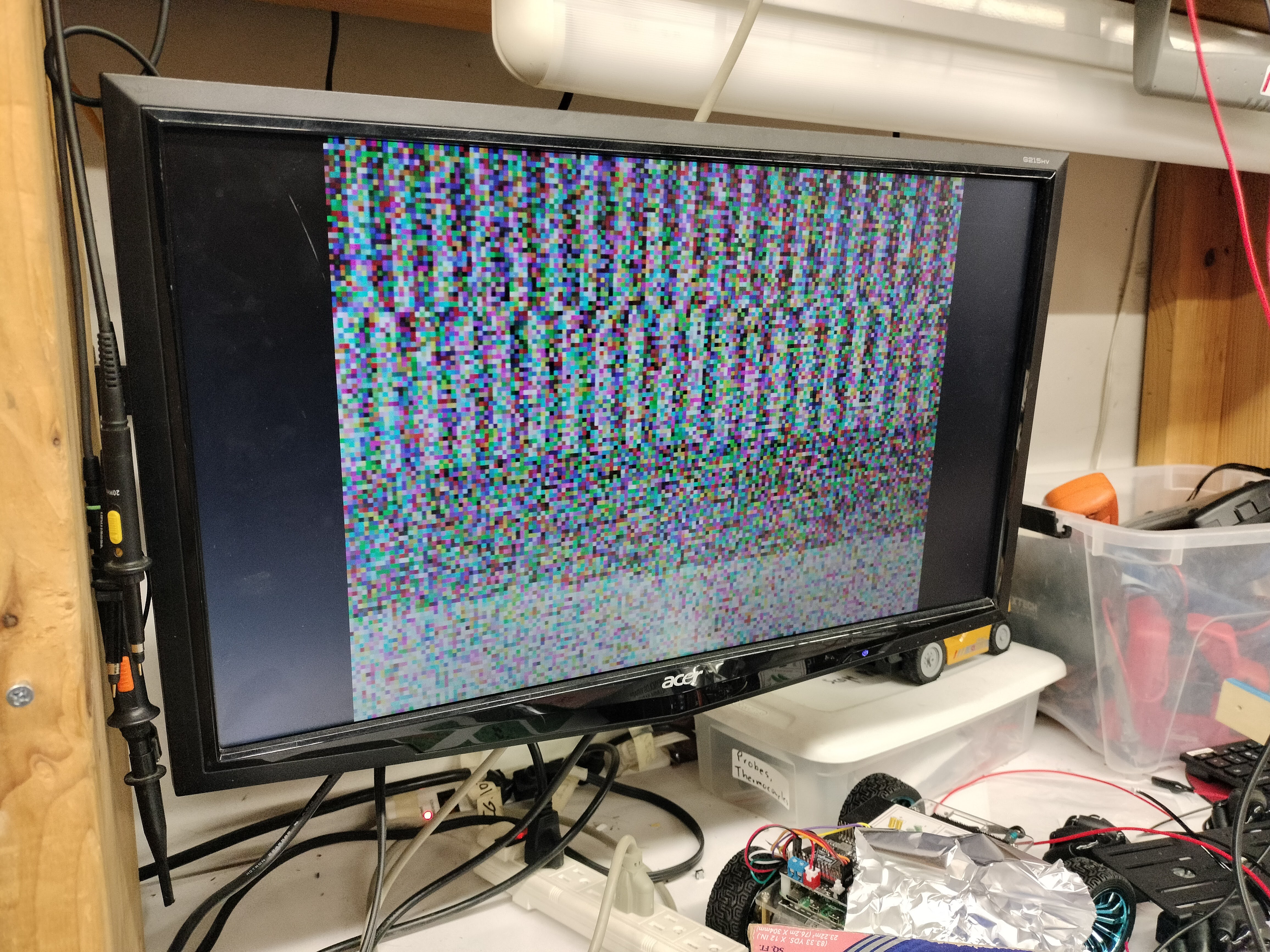 Power-on noise: this is expected! The SRAM does not have a deterministic state when powered on.
 Drawing to the screen works!
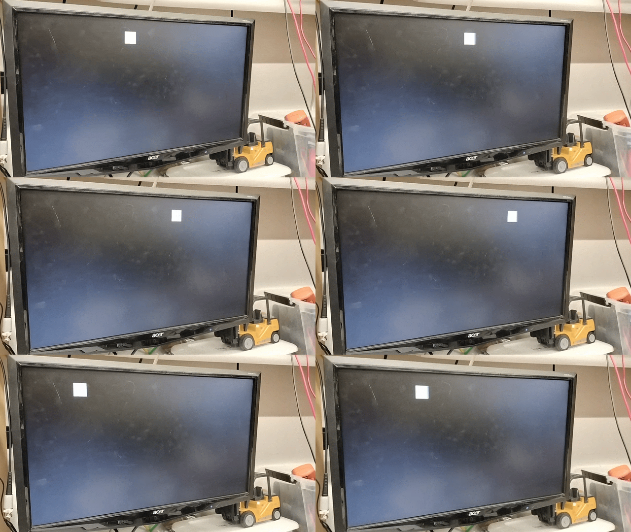 And it can redraw live!
| Qty | Value | Footprint | References |
|---|---|---|---|
| 34 | 0.1u | Capacitor_SMD:C_1206_3216Metric_Pad1.33x1.80mm_HandSolder | C1, C2, C10, C11, C12, C13, C14, C15, C16, C17, C18, C19, C20, C21, C22, C23 +18 |
| 8 | 74AHC30 | Package_SO:SOIC-14_3.9x8.7mm_P1.27mm | U10, U11, U12, U13, U21, U22, U23, U24 |
| 7 | Conn_01x03 | Connector_PinHeader_2.54mm:PinHeader_1x03_P2.54mm_Vertical | J6, J11, J12, J13, J14, J15, J18 |
| 6 | 74LV163 | Package_SO:SOIC-16_3.9x9.9mm_P1.27mm | U14, U17, U20, U26, U27, U28 |
| 4 | MountingHole | MountingHole:MountingHole_3.2mm_M3 | H1, H2, H3, H4 |
| 3 | 100 | Resistor_SMD:R_1206_3216Metric_Pad1.30x1.75mm_HandSolder | R9, R10, R11 |
| 3 | 74CBT16390 | Package_SO:TSSOP-56_6.1x14mm_P0.5mm | U5, U6, U9 |
| 3 | 74LV08 | Package_SO:SOIC-14_3.9x8.7mm_P1.27mm | U19, U32, U33 |
| 3 | Conn_01x02 | Connector_PinHeader_2.54mm:PinHeader_1x02_P2.54mm_Vertical | J1, J5, J22 |
| 2 | 1.8k | Resistor_SMD:R_1206_3216Metric_Pad1.30x1.75mm_HandSolder | R3, R6 |
| 2 | 470 | Resistor_SMD:R_1206_3216Metric_Pad1.30x1.75mm_HandSolder | R5, R8 |
| 2 | 74AC109 | Package_SO:SOIC-16_3.9x9.9mm_P1.27mm | U16, U25 |
| 2 | 74HC00 | Package_SO:SOIC-14_3.9x8.7mm_P1.27mm | U2, U4 |
| 2 | 74LV04 | Package_SO:SOIC-14_3.9x8.7mm_P1.27mm | U15, U18 |
| 2 | 74LV32 | Package_SO:SOIC-14_3.9x8.7mm_P1.27mm | U30, U31 |
| 2 | 910 | Resistor_SMD:R_1206_3216Metric_Pad1.30x1.75mm_HandSolder | R4, R7 |
| 2 | AS7C256A-10 | Package_SO:TSOP-I-28_11.8x8mm_P0.55mm | U7, U8 |
| 2 | Conn_01x04 | Connector_PinHeader_2.54mm:PinHeader_1x04_P2.54mm_Vertical | J19, J20 |
| 2 | Conn_01x08 | Connector_PinHeader_2.54mm:PinHeader_1x08_P2.54mm_Vertical | J2, J8 |
| 2 | Conn_01x10 | Connector_PinHeader_2.54mm:PinHeader_1x10_P2.54mm_Vertical | J9, J10 |
| 1 | 100n | Capacitor_SMD:C_1206_3216Metric_Pad1.33x1.80mm_HandSolder | C37 |
| 1 | 10u | Capacitor_SMD:C_1206_3216Metric_Pad1.33x1.80mm_HandSolder | C35 |
| 1 | 25.175MHz | Oscillator:Oscillator_DIP-8 | X1 |
| 1 | 330n | Capacitor_SMD:C_1206_3216Metric_Pad1.33x1.80mm_HandSolder | C36 |
| 1 | 390 | Resistor_SMD:R_1206_3216Metric_Pad1.30x1.75mm_HandSolder | R2 |
| 1 | 74HC377 | custom:SOIC-20_5.3x12.6mm_P1.27mm | U29 |
| 1 | 74HC86 | Package_SO:SOIC-14_3.9x8.7mm_P1.27mm | U1 |
| 1 | 74LV27 | Package_SO:SOIC-14_3.9x8.7mm_P1.27mm | U3 |
| 1 | 820 | Resistor_SMD:R_1206_3216Metric_Pad1.30x1.75mm_HandSolder | R1 |
| 1 | Barrel_Jack_Switch | Connector_BarrelJack:BarrelJack_CUI_PJ-102AH_Horizontal | J21 |
| 1 | Conn_01x01 | Connector_PinHeader_2.54mm:PinHeader_1x01_P2.54mm_Vertical | J16 |
| 1 | Conn_01x05 | Connector_PinHeader_2.54mm:PinHeader_1x05_P2.54mm_Vertical | J17 |
| 1 | Conn_01x16 | Connector_PinHeader_2.54mm:PinHeader_1x16_P2.54mm_Vertical | J4 |
| 1 | DE15_Receptacle_HighDensity | custom:DSUB-15-HD_Female_Horizontal_P2.29x1.98mm_EdgePinOffset8.35mm_Housed_MountingHolesOffset10.89mm | J7 |
| 1 | L7805 | Package_TO_SOT_THT:TO-220-3_Horizontal_TabDown | U34 |
| 1 | LOGO | custom:sky-standing | G*** |
| 1 | LOGO | custom:sky | G*** |
| 1 | LOGO | custom:salix | G*** |
| 1 | LOGO | custom:bnyahaj | G*** |
| 1 | LOGO | custom:alt | G*** |
| 1 | LOGO | custom:sky-headphones | G*** |
slu4coder/Minimal-64x4-Home-Computer
My DIY TTL home computer with VGA and PS/2 and 4x the processing power of a Commodore C64 or Apple II.

slu4coder/Minimal-UART-Computer-3
Version 3 of my educational DIY TTL computer built around a UART serial interface - now with blinkenlights!

otterbox901/8-Bit_CPU
Microcoded 8-bit CPU built from 24 74HC-series ICs: a custom 10-instruction ISA, 4 general-purpose registers, and an EEPROM-driven control unit.


rabid-inventor/mc68xx-boards
collection of PCB's based around the Motorola MC6800 series processor

EwoudVV/arpeggiator
12-note analog arpeggiator with a 1/2/3 octave range, custom pcb and printed case
It measures 140 × 110 mm and has 4 copper layers, 1.6 mm thick.
114 parts, built around the 74AHC30D, 74LV08PW, 74AC109PC and 74HC00D. The full list of its parts is on this page, with links to each part's symbol and footprint where PCBKit's library has them.
From the sky-dragn/6502fb repository on GitHub, at the commit this page was made from: the board is 6502fb.kicad_pcb and its schematic 6502fb.kicad_sch. PCBKit opens the board in the browser, with nothing to install.
Its repository states no licence, so its author keeps all rights: ask sky-dragn before reusing the design.