
4 layers98.7 × 104 mm

 skuep/AIOC1.4k
Ham Radio All-in-one-Cable
K1-aioc is an open-source printed circuit board by skuep, from the skuep/AIOC repository on GitHub, published under the MIT licence. It is a 2-layer board of 21 × 31.5 mm with 50 parts on 61 nets, routed with 487 tracks and 88 vias.
It is built around the MIC5330-SSYML, BC847BS and USB4105-GF-A. Its parts include 19 resistors, 16 capacitors, 4 diodes, 2 ICs and 2 connectors. It belongs with the radio and wireless boards and the STM32 boards of this library.


This is the Ham Radio All-in-one-Cable. It has been in testing stage for a long time, but so far no dealbreaking issues have been found so it is pretty safe to build it. Still, please read this README carefully before ordering anything.
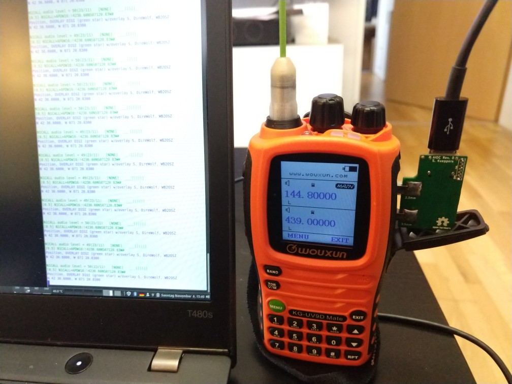
The AIOC is a small adapter with a USB-C connector that enumerates itself as a sound-card (e.g. for APRS purposes), a virtual tty ("COM Port") for programming and asserting the PTT (Push-To-Talk) as well as a CM108 compatible HID endpoint for CM108-style PTT (new in firmware version 1.2.0).
You can watch the videos of the Temporarily Offline and HAM RADIO DUDE YouTube channels below.
There is also a German 4-part article with instructions here.
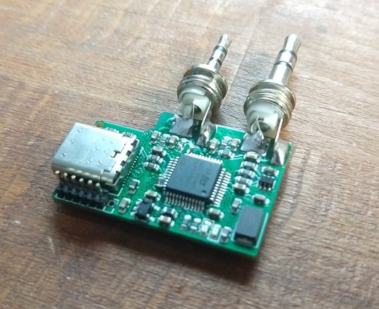
GERBER-k1-aioc.zip package (under kicad/k1-aioc/jlcpcb)
BOM-k1-aioc.csvCPL-k1-aioc.csvThis gives you 5 (or more) SMD assembled AIOC. The only thing left to do is soldering on the TRS connectors (see here). The total bill should be around 60$ US for 5 pieces plus tax and shipping from China.
Note that the following message from JLCPCB is okay and can be ignored.
The below parts won't be assembled due to data missing.
H1,H2 designators don't exist in the BOM file.
J2,D3,D4,R17 designators don't exist in the CPL file.
Note for people doing their own PCB production: I suggest using the LCSC part numbers in the BOM file as a guide on what to buy (especially regarding the MCU). Despite the STM32F373 in the BOM, the firmware currently only supports the STM32F302 as given in the LCSC ordering information.
Note As of 2025-09-25, the current hardware version is 1.2. The minimum firmware version for this hardware version is 1.4.0. The following features have been added.
This is the process I use for building. See photographs in images folder.
PG-204P and PG-203P or compatible TRS connectors (2 solder lugs and a big tab for the sleeve connection). Adafruit products 1800 and 1798 are confirmed to work as well.Note It is unfortunately quite common that the TRS connectors have intermittent contact after soldering the ring or tip tabs. In this case, it helps to re-melt the solder joint, then using e.g. tweezer slightly assert some sideways force onto the contact and let the solder joint solidify while applying the pressure on the contact. This will keep some tension on the area where the tab internally connects to the barrel and thus give a solid (spring loaded) connection.
For building the firmware, clone the repository and initialize the submodules. Create an empty workspace with the STM32CubeIDE and import the project.
git clone <repositry url>git submodule update --init<project-root>/stm32aioc-fw project in the same folder without copyingThe following steps are required for initial programming of the AIOC:
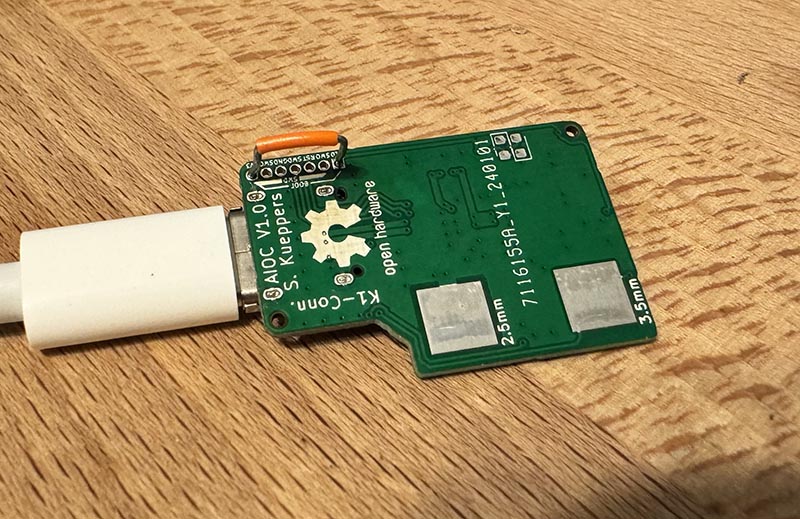
dfu-util to program the firmware binary from the GitHub Releases page like this:
dfu-util -a 0 -s 0x08000000:leave -D aioc-fw-x-y-z.binlibusb driver is required for this. On Windows there are additional steps required as shown here (DFuSe Utility and dfu-util). On other operating systems (e.g. Linux, MacOS), this just works ™ (provided libusb is installed on your system).
On Linux (and MacOS), your user either needs to have the permission to use libusb (plugdev group) or you might need to use sudo.Once the AIOC has firmware loaded onto it, it can be re-programmed without the above BOOT sequence by following these steps.
Note This requires firmware version >= 1.2.0. For older firmwares, the initial programming sequence above is required for updating the firmware.
dfu-util like this
dfu-util -d 1209:7388 -a 0 -s 0x08000000:leave -D aioc-fw-x-y-z.binThis will reboot the AIOC into the bootloader automatically and perform the programming. After that, it automatically reboots the AIOC into the newly programmed firmware.
Note Should you find yourself with a bricked AIOC, use the initial programming sequence above
The serial interface of the AIOC enumerates as a regular COM (Windows) or ttyACM port (Linux) and can be used as such for programming the radio as well as PTT (Asserted on DTR=1 and RTS=0).
Note before firmware version 1.2.0, PTT was asserted by DTR=1 (ignoring RTS) which caused problems with certain radios when using the serial port for programming the radio e.g. using CHIRP.
The soundcard interface of the AIOC gives access to the audio data channels. It has one mono microphone channel and one mono speaker channel and currently supports the following baudrates:
Since firmware version 1.2.0, a CM108 style PTT interface is available for public testing. This interface works in parallel to the COM-port PTT. Direwolf on Linux is confirmed working, please report any issues. Note that currently, Direwolf reports some warnings when using the CM108 PTT interface on the AIOC. While they are annoying, they are safe to ignore and require changes in the upstream direwolf sourcecode. See https://github.com/wb2osz/direwolf/issues/448 for more details.
Since firmware version 1.3.0, a HID interface is also available, that allows reconfiguration of the AIOC from the PC. There are code snippets in the Release Notes for various features. There is also a command-line utility by Hrafnkell Eiríksson available here.
For advanced use of the AIOC, refer to this pinout image.
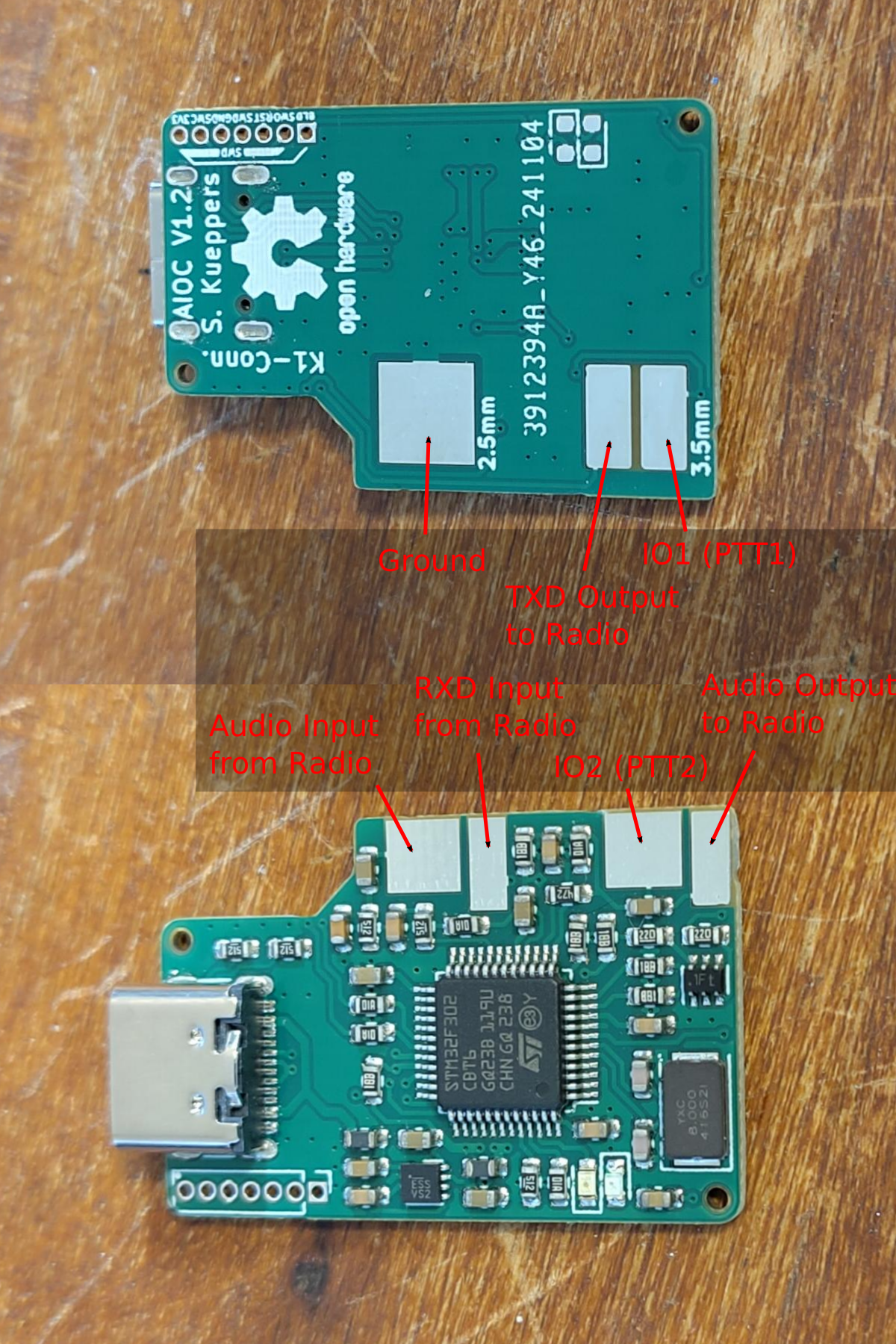
[...]
ADEVICE plughw:<x>,0  # <- Linux
ADEVICE x 0           # <- Windows
ARATE 48000
[...]
PTT CM108             # <- Use the new CM108 compatible style PTT interface
PTT <port> DTR -RTS   # <- Alternatively use an old school serial device for PTT
[...]Once your cable is emulating a CM108, it becomes quite simple to plug into your HT and setup a simple simplex AllStarLink node that talks to your favorite repeater or node.
In asl-menu, set:
usbradio (menu sections: 2 > A1 > N4 > I2)1 (menu sections: 2 > A1 > N5)Edit usbradio.conf (menu sections: 6 > H) (for a Puxing PX-888 cheap Chineese HT)
rxboost = 0rxsqhyst = 500carrierfrom = usbinvertctcssfrom = norxdemod = speakertxprelim = noinvertptt = noAPRSdroid support has been added by AIOC by implementing support for the fixed 22050 Hz sample rate that APRSdroid requires. It is important to notice, that the exact sample rate can not be achieved by the hardware, due to the 8 MHz crystal. The actual sample rate used is 22052 Hz (which represents around 90 ppm of error). From my testing this does not seem to be a problem for APRS at all.
However, since APRSdroid does not have any PTT control, sending data is currently not possible using the AIOC except using the radio VOX function. See https://github.com/ge0rg/aprsdroid/issues/324. My previous experience is, that the Android kernel brings support for ttyACM devices (which is perfect for the AIOC) so implementing this feature for APRSdroid should theoretically be no problem.
Ideas such as implementing a digital-modes-spefic VOX-emulation to workaround this problem and let the AIOC activate the PTT automatically are currently being considered. Voice your opinion and ideas in the GitHub issues if this seems interesting to you.
CHIRP is a very popuplar open-source programming software that supports a very wide array of HT radios. You can use CHIRP just as you would like with a regular programming cable.
Download:
Upload:
Select "DTR only" for PTT Pin, so that the correct RTS/DTR sequence is generated for PTT
There are known issues with EMI, when using a handheld radio with a monopole (i.e. stock) antenna. In this case, the USB cable will (inadvertently) work as a tiger-tail (counterpoise) and thus, high RF currents go through the USB lines which cause issues with the USB connection. Some people have connected cables between the radio and the AIOC and put a ferrite core on those wires, which seems to reduce those issues. I am trying to find out, which of the wires between the radio and the AIOC produce the problem, so that we might add SMD ferrites on the AIOC in the future
As a workaround, you can try to reduce the transmit power or use a tiger-tail (counterpoise). Additionally, a good solution is to use a balanced antenna, such as my EZ-Dipole.
| Qty | Value | Footprint | References |
|---|---|---|---|
| 7 | 4.7u/10V/X5R | Capacitor_SMD:C_0603_1608Metric | C4, C5, C6, C7, C10, C13, C14 |
| 6 | 1.5K | Resistor_SMD:R_0603_1608Metric | R1, R4, R10, R11, R18, R19 |
| 6 | 100n | Capacitor_SMD:C_0603_1608Metric | C3, C8, C9, C12, C15, C16 |
| 5 | 100R | Resistor_SMD:R_0603_1608Metric | R3, R8, R9, R15, R17 |
| 5 | 5.1K | Resistor_SMD:R_0603_1608Metric | R5, R6, R7, R14, R16 |
| 2 | 22R | Resistor_SMD:R_0603_1608Metric | R12, R13 |
| 2 | 22p/NP0 | Capacitor_SMD:C_0603_1608Metric | C1, C2 |
| 2 | 600R@100MHz | Inductor_SMD:L_0603_1608Metric | FB1, FB2 |
| 2 | N.M. | LED_SMD:LED_0603_1608Metric | D3, D4 |
| 2 | ToolingHole | AIOC:TOOLING-HOLE | H1, H2 |
| 1 | 4.7K | Resistor_SMD:R_0603_1608Metric | R2 |
| 1 | 4.7n/NP0 | Capacitor_SMD:C_0603_1608Metric | C11 |
| 1 | 8MHz/20pF | AIOC:Crystal_SMD_5032-2Pin_5.0x3.2mm | Y1 |
| 1 | BC847BS | Package_TO_SOT_SMD:SOT-363_SC-70-6 | Q1 |
| 1 | Conn_01x07_Male | Connector_PinHeader_1.27mm:PinHeader_1x07_P1.27mm_Vertical | J2 |
| 1 | GREEN | LED_SMD:LED_0603_1608Metric | D1 |
| 1 | MIC5330-SSYML | AIOC:Micrel_MLF-8-1EP_2x2mm_P0.5mm_EP0.6x1.2mm | U1 |
| 1 | RED | LED_SMD:LED_0603_1608Metric | D2 |
| 1 | STM32F373CBTx | Package_QFP:LQFP-48_7x7mm_P0.5mm | U2 |
| 1 | USB4105-GF-A | AIOC:USB_C_Receptacle_GCT_USB4105-xx-A_16P_TopMnt_Horizontal | J1 |
The 49 most common of 50 parts.
It measures 21 × 31.5 mm and has 2 copper layers, 1.2 mm thick.
50 parts, built around the MIC5330-SSYML, BC847BS and USB4105-GF-A. The full list of its parts is on this page, with links to each part's symbol and footprint where PCBKit's library has them.
From the skuep/AIOC repository on GitHub, at the commit this page was made from: the board is kicad/k1-aioc/k1-aioc.kicad_pcb and its schematic kicad/k1-aioc/k1-aioc.kicad_sch. PCBKit opens the board in the browser, with nothing to install.
Its repository publishes it under the MIT licence: you may reuse it on that licence's terms (keep the author's notice, and for a copyleft licence share your changes alike).


OpenTaxus/opentaxus
Opentaxus is a permissively licensed set of hardware, software, and tooling to help as a starting point for customized conference badges.


