2 layers
Nrf bga
github-linguist/linguist
Language Savant. If your repository's language is being reported incorrectly, send us a pull request!
12 parts14kMIT

 skogaby/KFChickenShim19
A PCB to allow SDVX 4 cabinets to easily upgrade to newer versions.
KFChickenShim is an open-source printed circuit board by skogaby, from the skogaby/KFChickenShim repository on GitHub, published under the MIT licence. It is a 2-layer board of 99.2 × 48.9 mm with 12 parts on 20 nets, routed with 35 tracks and 0 vias.
So, you bought a Sound Voltex 4 cabinet, but weren't able to secure an official or clone upgrade kit for Sound Voltex V?
This is KFChickenShim, a simple PCB that adapts the various JST connectors found on a Sound Voltex IV IO board (known as KFCA) to standard connectors that allow you to easily connect the board to an off-the-shelf PC. Doing this, you can utilize a solution known as KFChicken, combined with SpiceTools, to run SDVX 5 or newer inside an older cabinet, complete with full IO, card reader, working lights, headphone support, etc. In addition, there is no perceivable latency or negative affect on gameplay, though your in-game offsets may not be what you're typically used to and might need adjustment for the new setup.
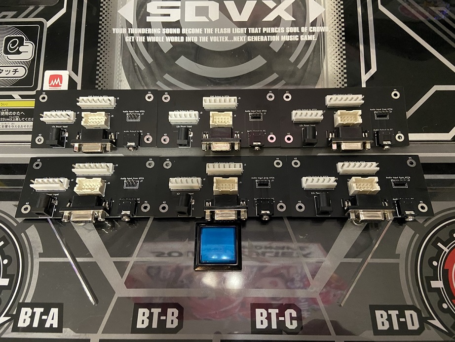
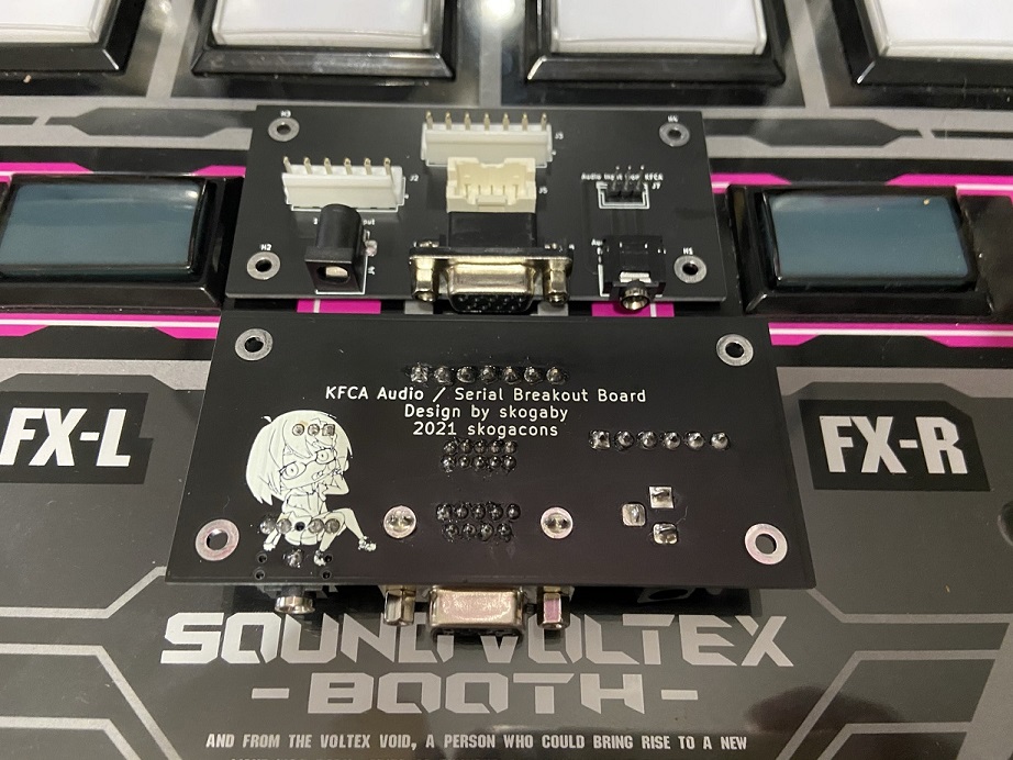
If you buy a pre-made PCB from me, you'll need the following:
Additionally, if you're ordering and assembling your own PCB, you'll need the following connectors:
Here are the instructions for setting up the board for use. I will not cover PCB assembly, all of the components are pretty self-explanatory in terms of placement on the board (they all have exactly one spot).
The first thing you'll want to do is remove the original BemaniPC from the cabinet. You'll need to disconnect every cable and remove the PC entirely, as the KFCA board is inside the PC case. In the below image, the board in the red rectangle is the one we're after.
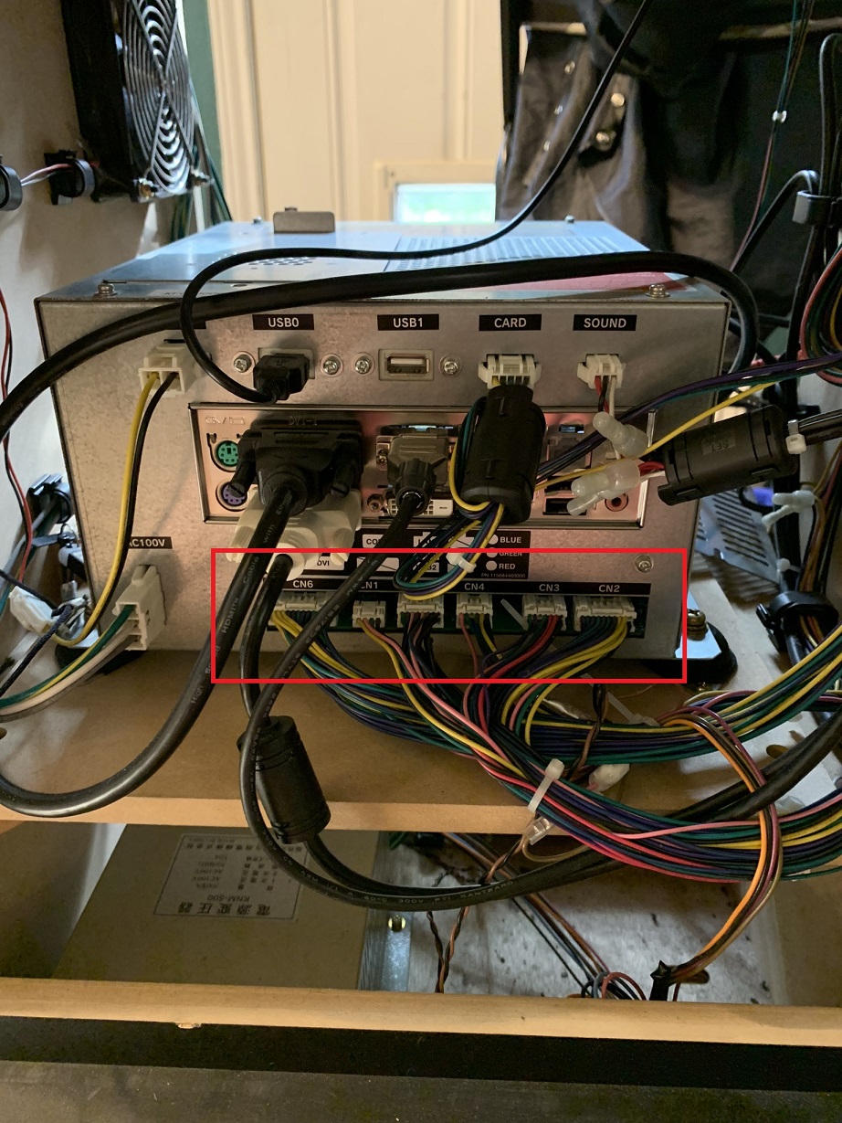
Once the PC is removed from the cabinet, you'll need to remove the KFCA board from inside the PC case, which means you'll need to unscrew the case of the BemaniPC so you can get inside it. NOTE: If your cab is a gen 1 cabinet, your PC may look different from mine, but the process should be similar in terms of removing the IO.
Once the top is removed, you should see the exposed motherboard of the original PC. You'll more or less want to unplug all cables from the motherboard, to make it easy to remove since the KFCA sits underneath the motherboard. In the picture below, the connector in the red rectangle is the serial coming from the KFCA, and will be plugged into the KFChickenShim board.
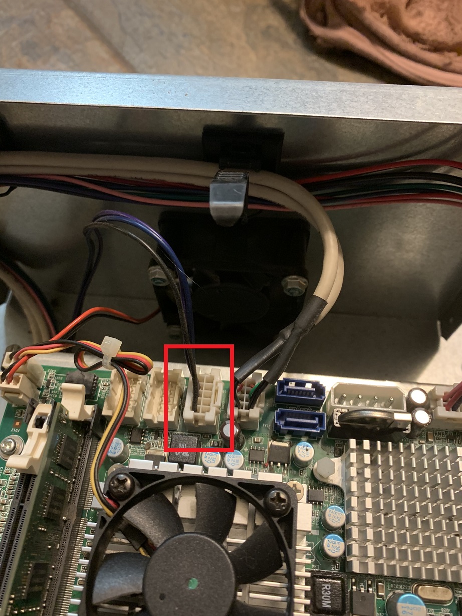
Once the motherboard is removed entirely, you'll be greeted with a view similar to below.
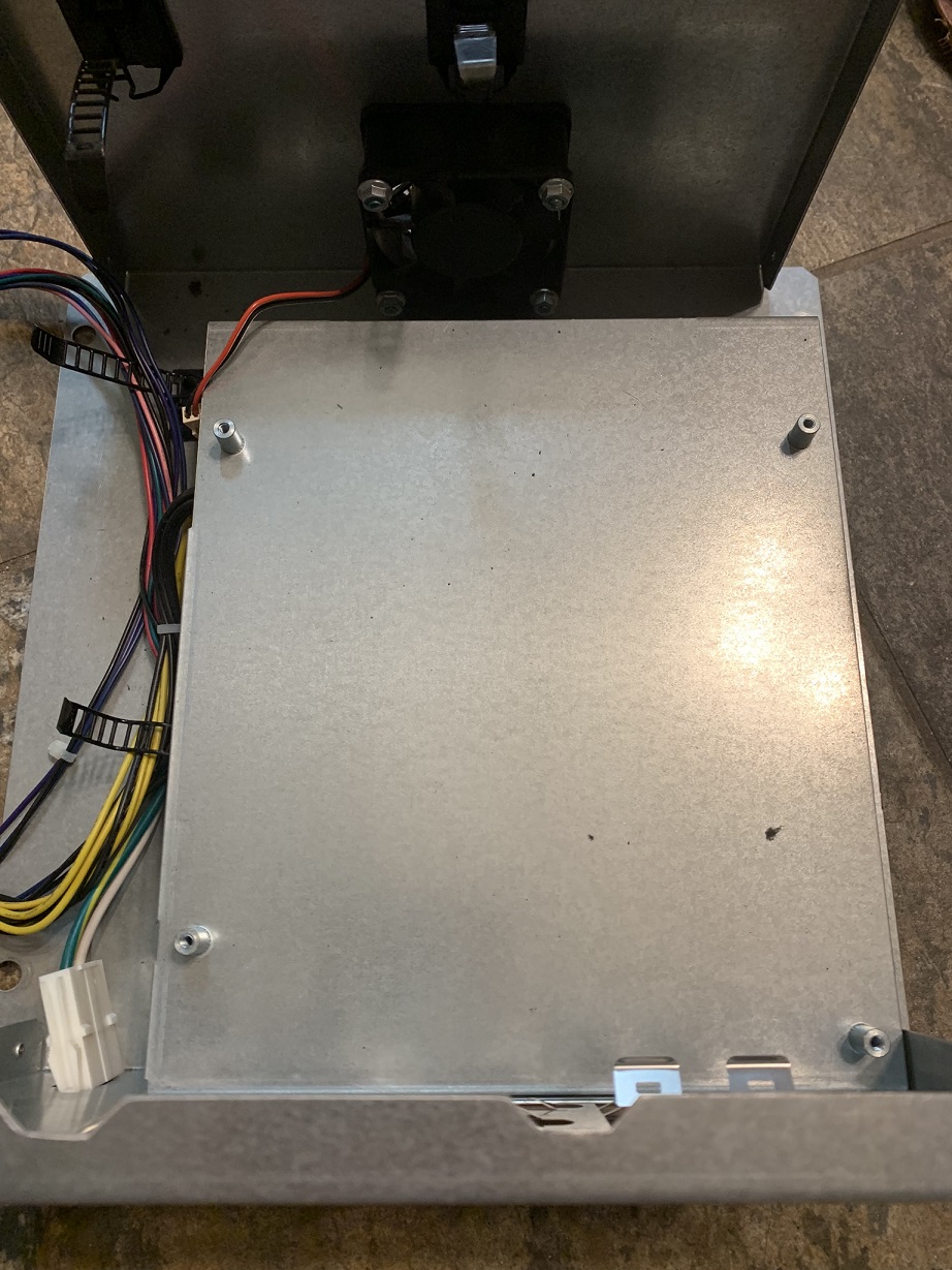
Go ahead and remove the metal plate that the motherboard was mounted to. Below it, you should see the KFCA board itself, as well as the power supply unit for the PC and the KFCA board.
KFCA Board
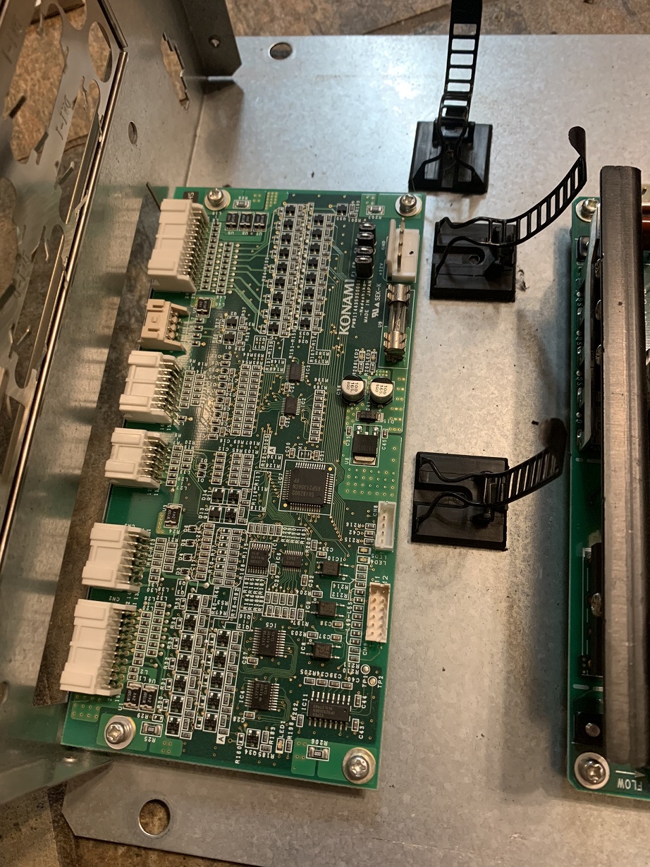
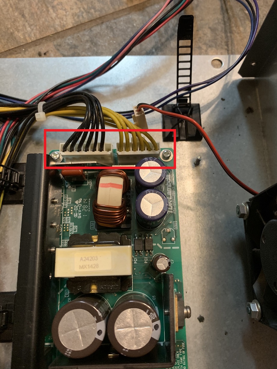
Power supply, with power connectors for the KFCA board
Once you unscrew the KFCA board, it should be free and ready for use.
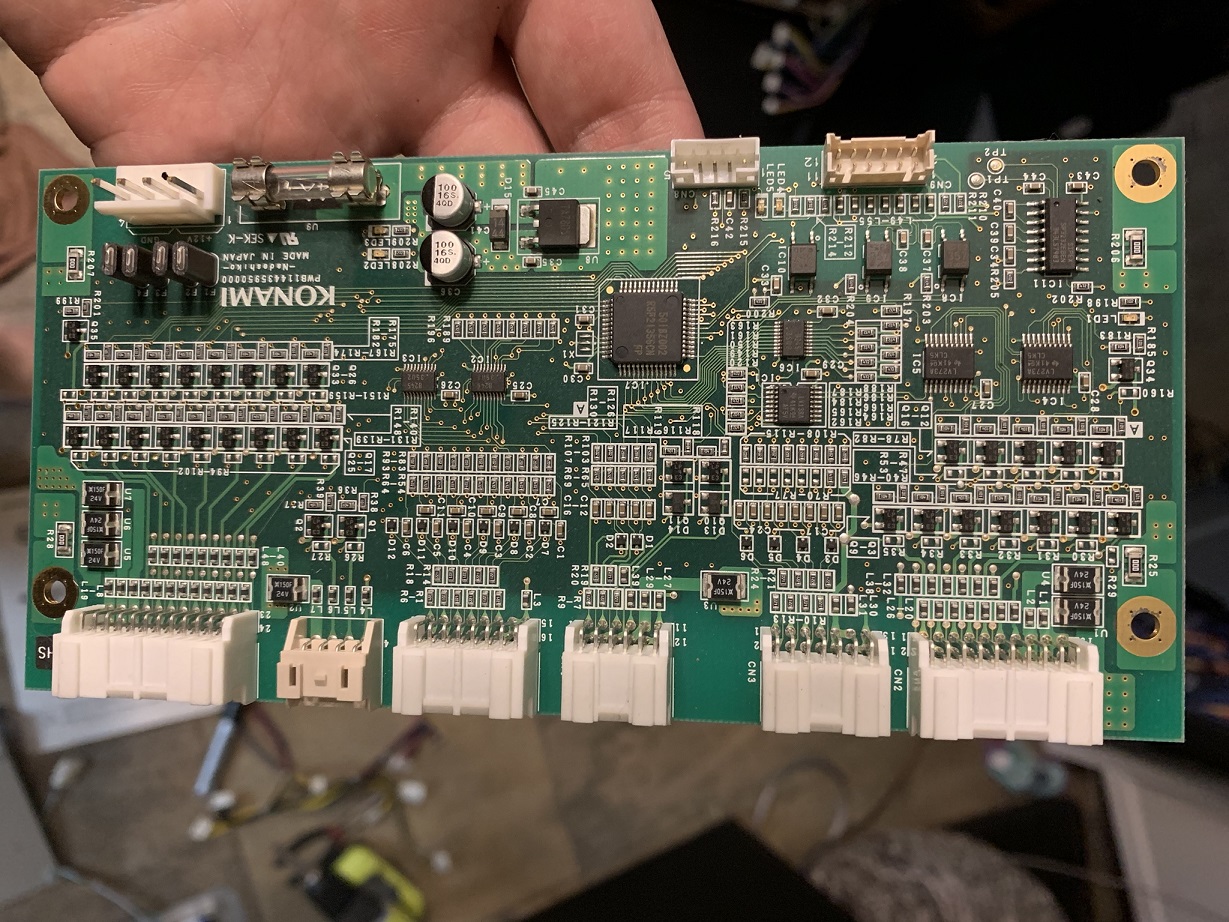
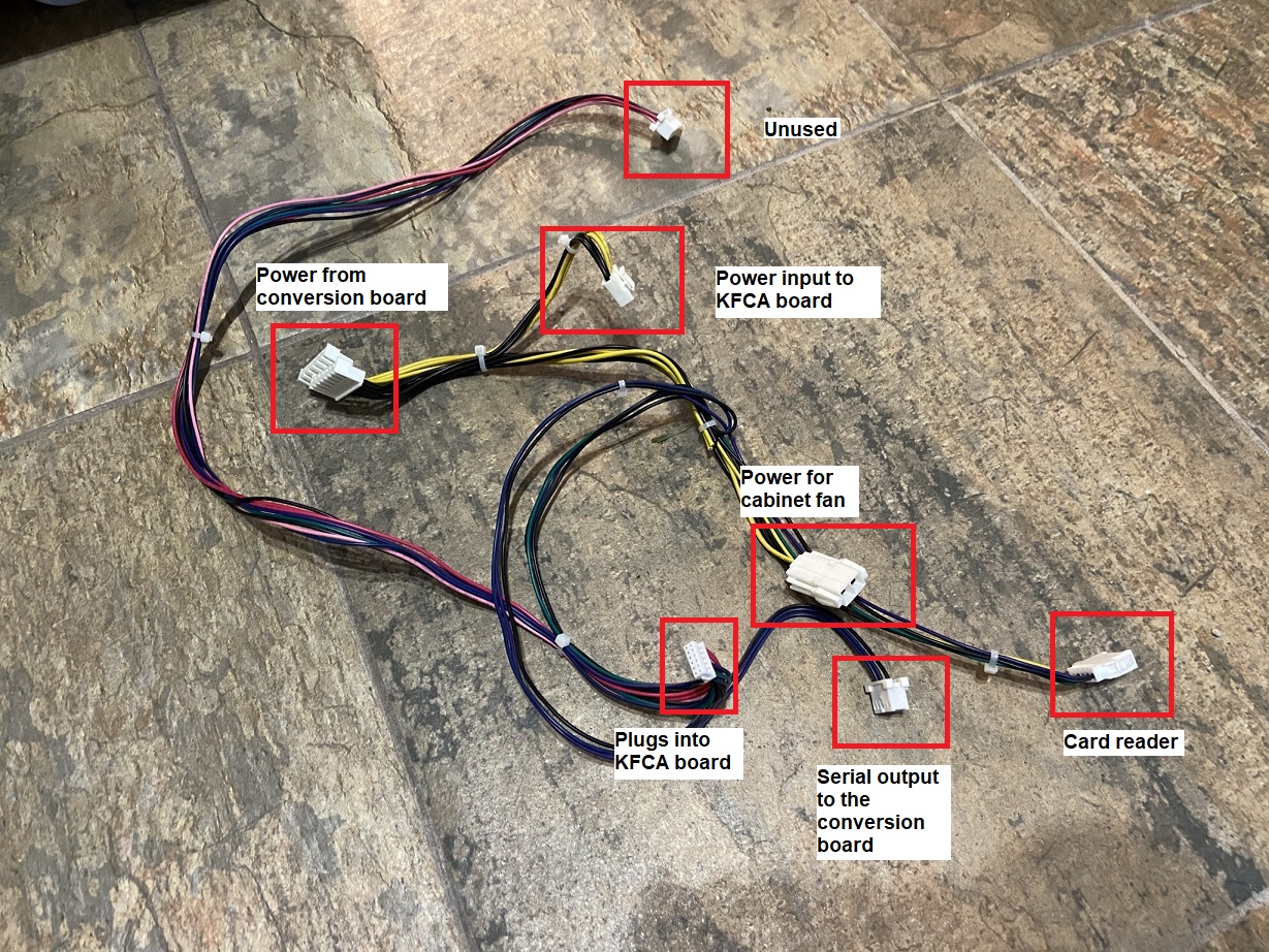
Below is the wiring harness that you should now have onhand for the KFCA board. Yours probably also has a plug that previously powered the PC, I just cut that off of mine since it's no longer being used. The wiring harness in the image is labeled appropriately, as we'll be referring to these later during assembly.
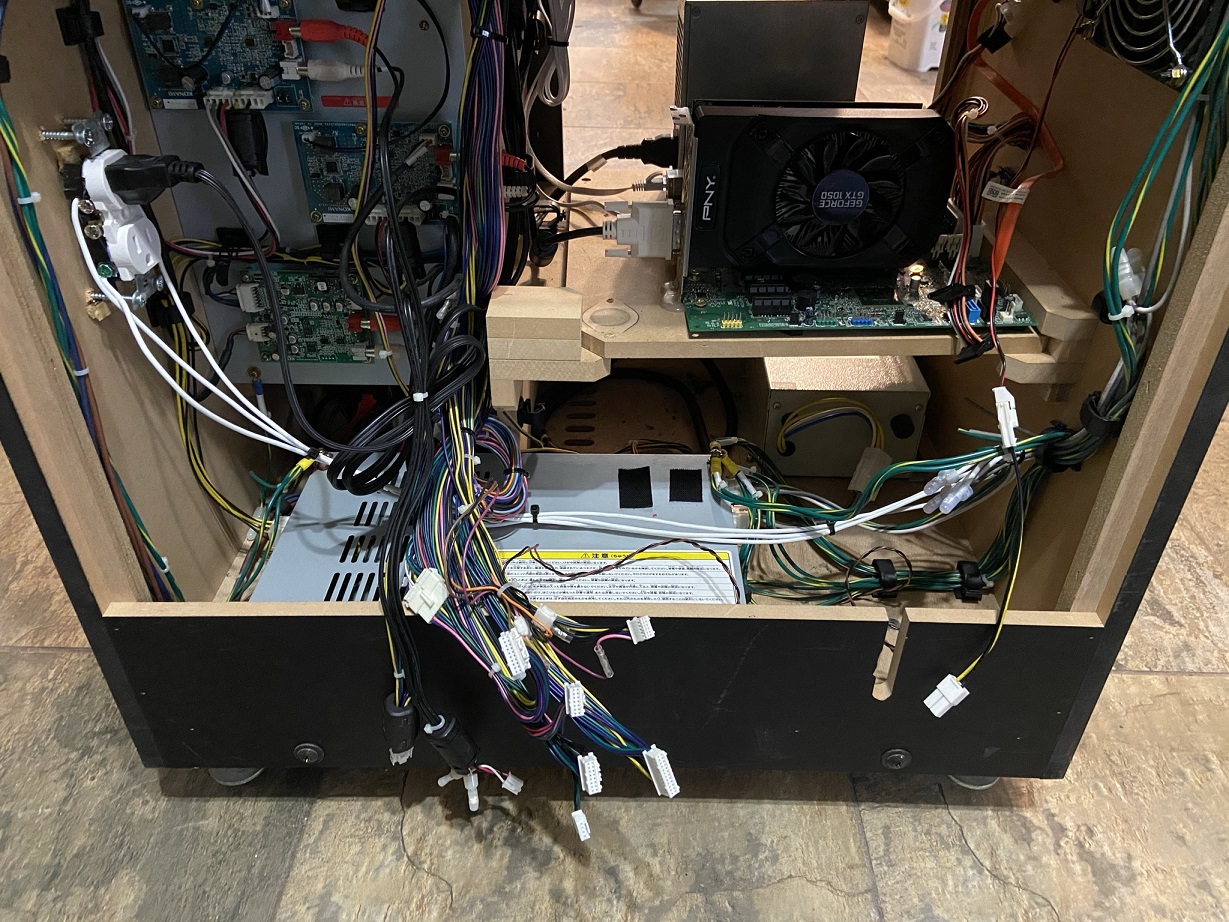
NOTE: I am NOT going to cover how to install the PC itself into your cabinet. This step can vary wildly depending on your setup. However, here is a picture of my personal cabinet, with a new PC installed and the IO removed. Please note that most cabinets have a 120v passthrough outlet sort of dangling at the end of a cord inside the cabinet. I highly recommend using this to power everything, but I had to pull that cable out of my cab for a different machine that needed one, so I spliced a regular wall outlet into the cab's power supply's 120v out. If you go this route, install an outlet cover box over the outlet (not pictured here).
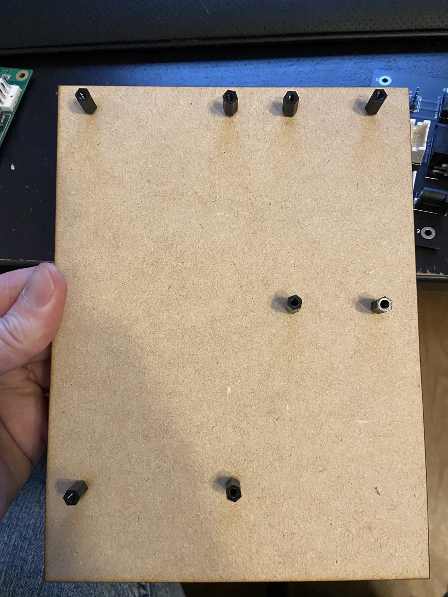
I'd also recommend making some sort of board like below with actual PCB/motherboard standoffs screwed into the wood. This will let you mount the PCBs inside the cab cleanly.
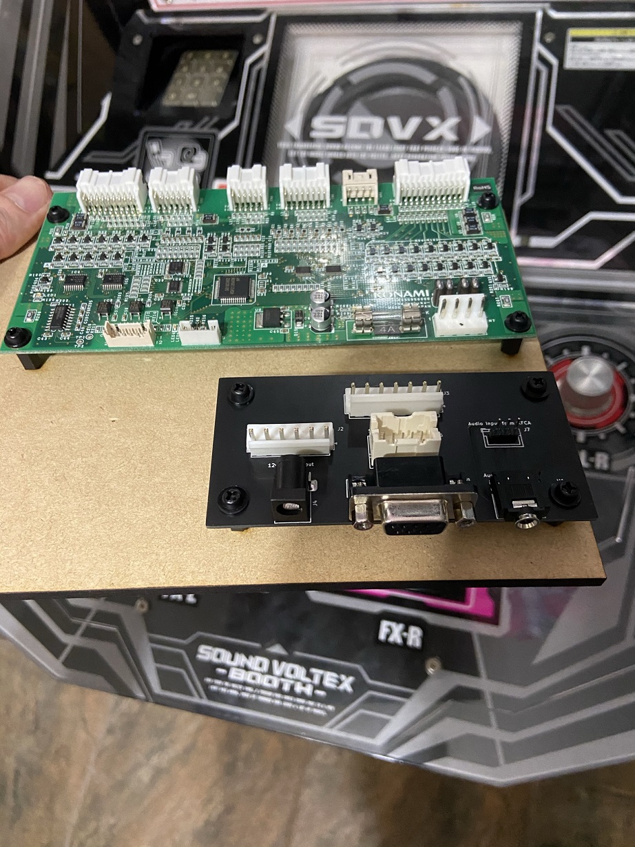
Go ahead and hook up the cables to the KFCA that are dangling inside the cabinet that previously connected to the front of the BemaniPC.
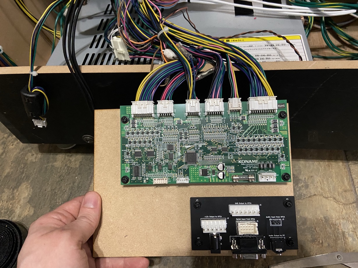
Next, connect the power connections from the KFChickenShim board to the KFCA via the wiring harness pulled from the original cabinet. Yellow is 12v, black is ground.
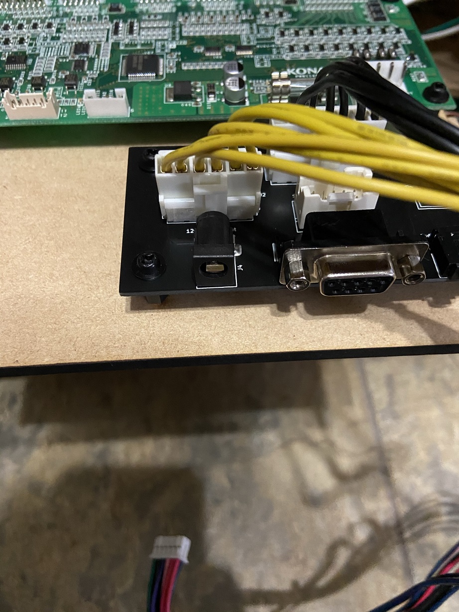
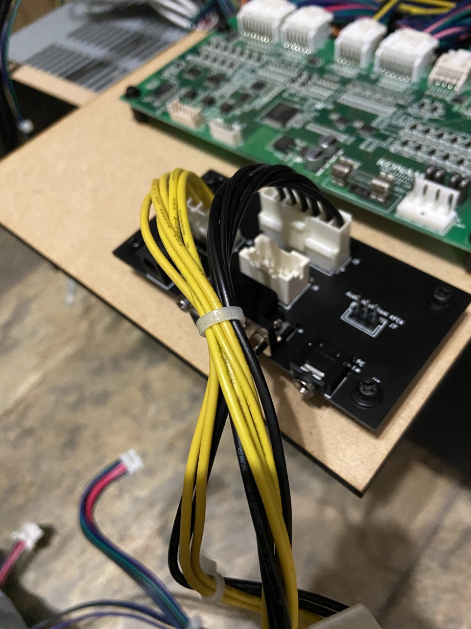
Now connect the power cable to the KFCA board itself from the wiring harness.
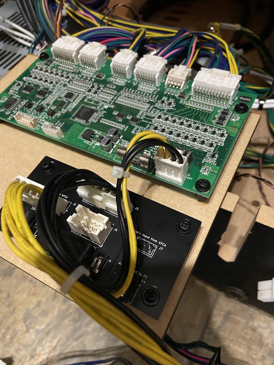
Next, connect the wiring harness power for the cabinet fan that sits next to the PC.
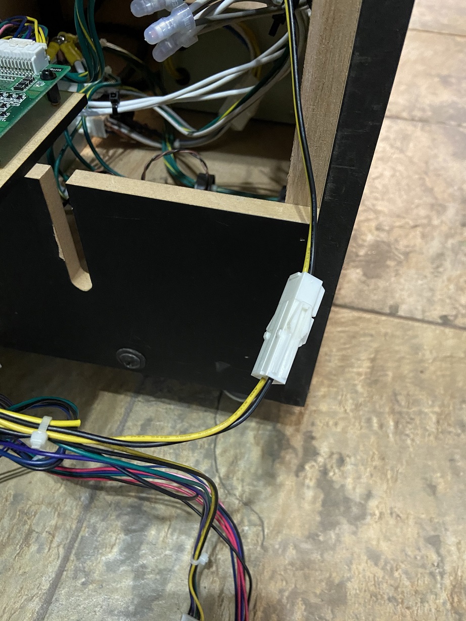
Connect the audio connector that's inside the cabinet (should be connected to 3 sets of red/white RCA cables on the other end) to the KFChickenShim board. Note the orientation of the plug, if it's plugged in backwards your left and right audio will be swapped.
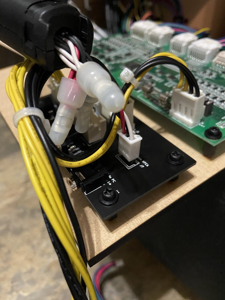
Connect the card reader to the wiring harness from the KFCA.
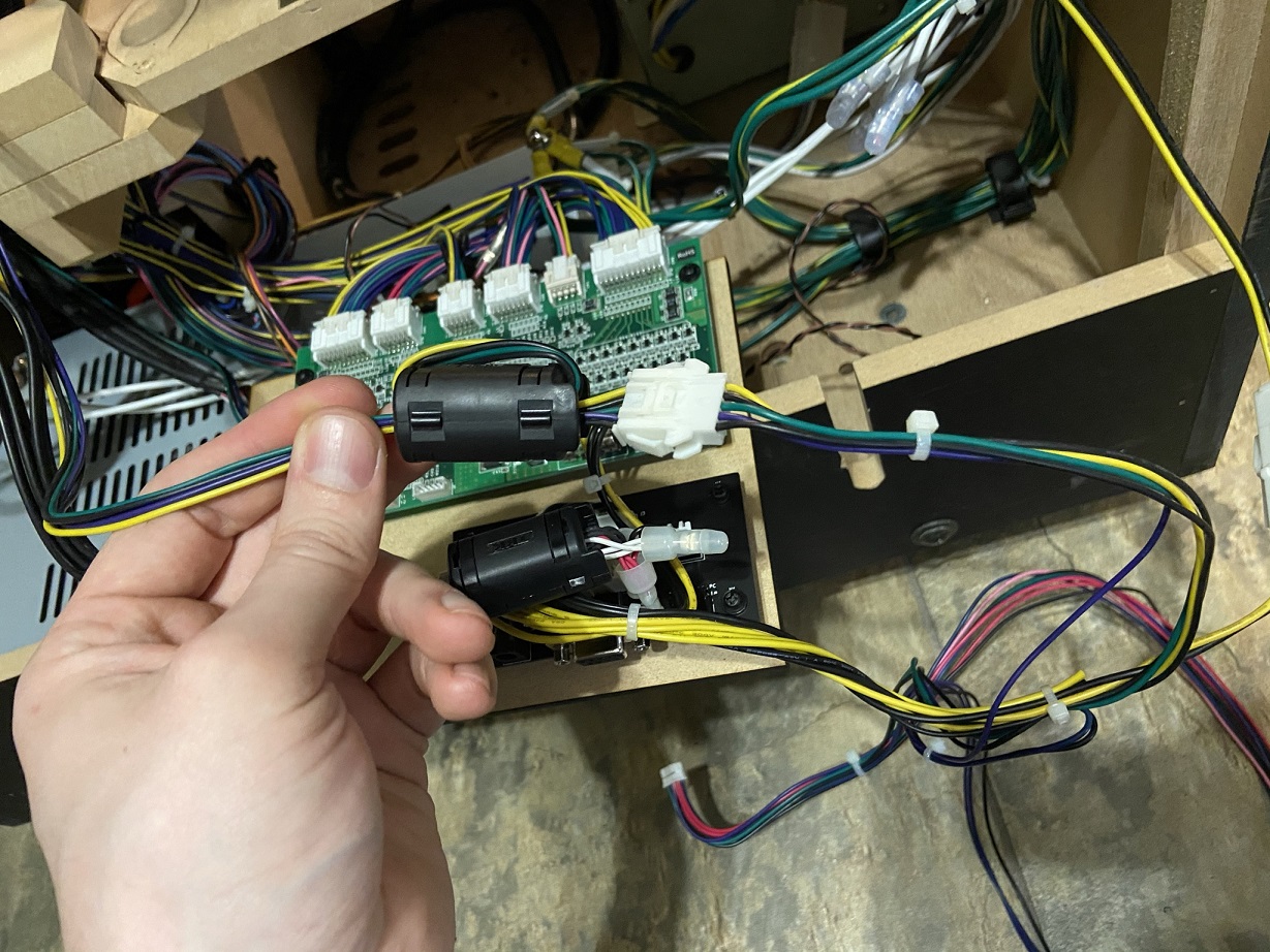
Connect the serial from the wiring harness to the KFChickenShim board.
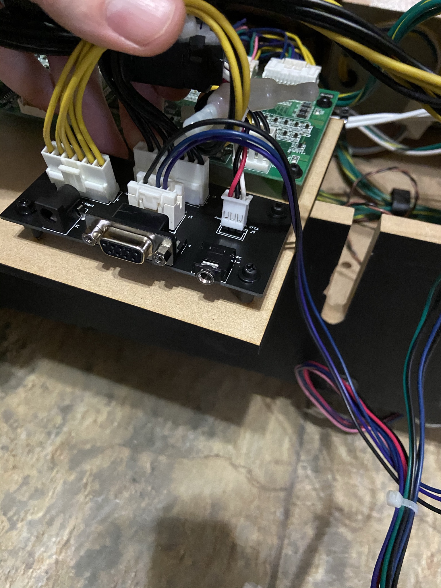
Connect this plug from the wiring harness to the KFCA board.
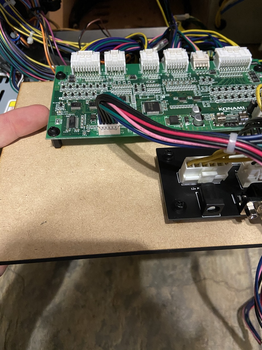
Connect the power input, serial cable, and audio cables to the KFChickenShim board and connect it to the new PC.
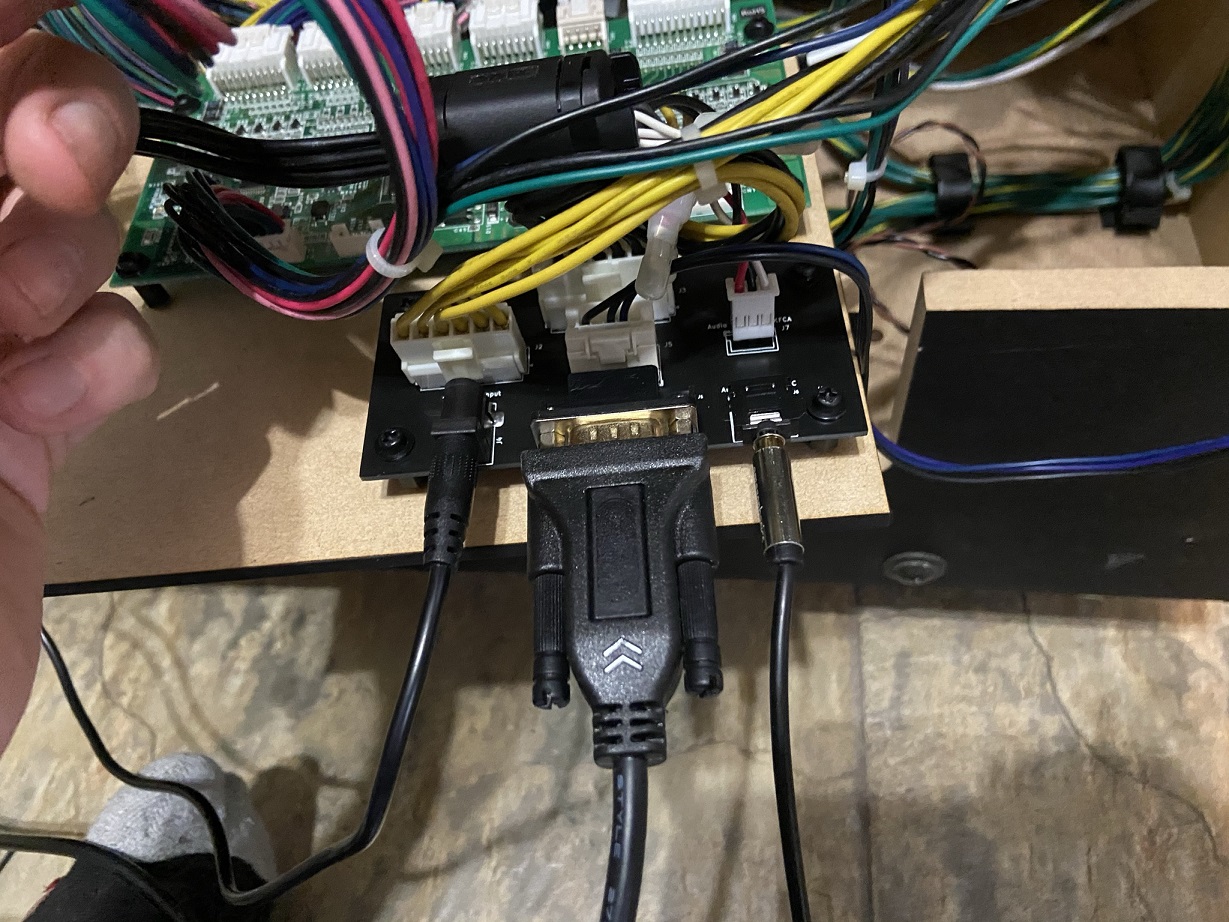
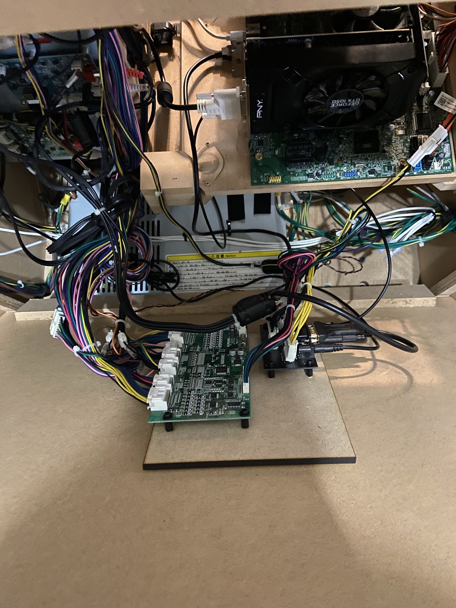
Almost there! I'd recommend mounting the board like this to the inside of the cabinet rear panel. I used velcro strip to attach the board to the rear door, in case I need to remove the rear door entirely.
If you power the cabinet on, you should see one red light on the KFCA, as well as one flashing light.
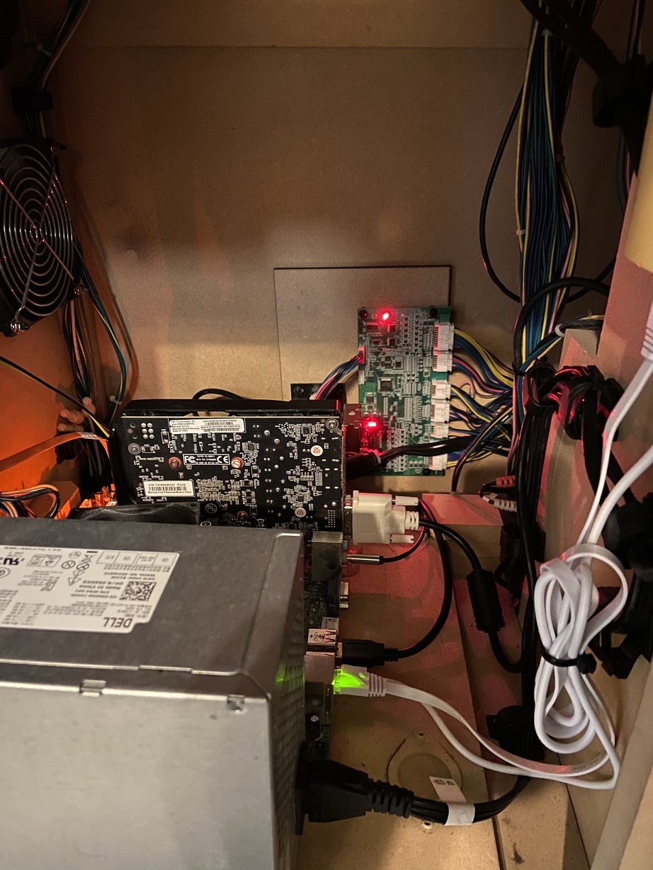
Hopefully this is the end of your hardware journey. Read the notes below for important tips when installing the software side of things.
Generally, just follow the KFChicken release thread's instructions for setting everything up, but here's a quick rundown and note the bolded item in particular:
libacio.dll file from your SDVX 4 installation and paste it into your SDVX 5 installation, renaming it to libacio32.dll.kfchicken32.dll and kfchicken32.exe into your SDVX 5 installation. The KFChicken release thread says you can use the 64-bit version and the SDVX 5 DLLs but this doesn't work correctly as of this writing, so use the SDVX 4 modules and 32-bit KFChicken.kfchicken.json file as below, making sure to change the com field to the appropriate COM port to match whatever serial port the KFCA is hooked up to (can be found using Windows Device Manager, under Ports (COM and LPT)), and also the right settings to match your SpiceAPI port and password in gamestart.bat (covered next). NOTE: The default kfchicken.json file has the baudrate field set to 57600. I personally experienced unplayable knobs/analog inputs until I changed this value to 115200 instead.{
"acio_dll": "libacio32.dll",
"com": 2,
"baudrate": 115200,
"host": "localhost",
"port": 1337,
"pass": "changeme",
"boot_delay": 500,
"poll_delay": 0,
"soft_fail": false,
"parse_cmd_line_args": true,
"debug_hook": false,
"watchdog_enable": false,
"watchdog_time": 120000,
"icca_enable": true,
"icca_limit": 1500,
"kfca_enable": true,
"coin_enable": true,
"coin_blocker_delay": 500,
"volume_enable": true,
"volume_sync": true,
"volume_sound_default": 20,
"volume_sound_limit": 0,
"volume_woofer_default": 20,gamestart.bat file to start KFChicken before starting Spice, and also to make Spice expose its API. Change the port and password to whatever you'd like, but make sure the kfchicken.json file has the same settings.start ./kfchicken32.exe
start ./spice64.exe -api 1337 -apipass changeme -sdvx
| Qty | Value | Footprint | References |
|---|---|---|---|
| 4 | Mount | MountingHole:MountingHole_3.2mm_M3_Pad | H1, H2, H3, H4 |
| 1 | +12v to KFCA | Connector_JST:JST_VH_B6P-VH_1x06_P3.96mm_Vertical | J2 |
| 1 | 3.5mm Audio to PC | SparkFun-Connectors:AUDIO-JACK | J6 |
| 1 | Audio from KFCA | Connector_JST:JST_XH_B3B-XH-A_1x03_P2.50mm_Vertical | J7 |
| 1 | Barrel_Jack | Connector_BarrelJack:BarrelJack_Horizontal | J4 |
| 1 | DB9FEMALE | SparkFun-Connectors:DB9 | J1 |
| 1 | GND to KFCA | Connector_JST:JST_VH_B7P-VH_1x07_P3.96mm_Vertical | J3 |
| 1 | LOGO | KFChickenShim:skogalogo | G*** |
| 1 | Serial from KFCA | Connector_JST_Better:JST_XAD_B10B-XADSS-N_2x05_P2.50mm_Vertical | J5 |
github-linguist/linguist
Language Savant. If your repository's language is being reported incorrectly, send us a pull request!


google/mozc-devices
Circuit diagrams and firmware source code for Gboard DIY keyboards


hackclub/OnBoard
💡 Join 1,000 teenagers and make your first PCB with a $100 grant!

VoronDesign/Voron-Tap
Tap is a nozzle-based z-probe for the V2 and Trident printer designs. The entire toolhead moves to trigger an optical switch. Tap offers many advantages:

stacksmashing/pico-tpmsniffer
A simple, very experimental TPM sniffer for LPC bus
It measures 99.2 × 48.9 mm and has 2 copper layers, 1.6 mm thick.
12 parts. The full list of its parts is on this page, with links to each part's symbol and footprint where PCBKit's library has them.
From the skogaby/KFChickenShim repository on GitHub, at the commit this page was made from: the board is PCB Files/KFChickenShim.kicad_pcb. PCBKit opens the board in the browser, with nothing to install.
Its repository publishes it under the MIT licence: you may reuse it on that licence's terms (keep the author's notice, and for a copyleft licence share your changes alike).