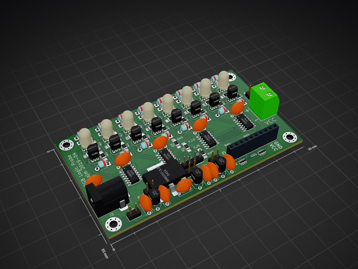
2 layers95 × 55 mm
 sjm42/electronics
Various electronics projects
Logic probe is an open-source printed circuit board by sjm42, from the sjm42/electronics repository on GitHub, published under the Apache-2.0 licence. It is a 2-layer board of 95 × 55 mm with 103 parts on 74 nets, routed with 566 tracks and 47 vias.
It is built around the LM339, AMS1117-3.3 and L78L05CZ, with the L78L10ACU, L78L15ABU and 2N2222A among its other parts. Its parts include 32 diodes, 27 resistors, 11 capacitors, 8 ICs and 8 transistors. It belongs with the sensors and measurement boards of this library.


My various electronics projects
| Qty | Value | Footprint | References |
|---|---|---|---|
| 24 | 1N4148 | Diodes_ThroughHole:D_T-1_P5.08mm_Horizontal | D0.1, D0.2, D0.3, D1.1, D1.2, D1.3, D2.1, D2.2, D2.3, D3.1, D3.2, D3.3, D4.1, D4.2, D4.3, D5.1 +8 |
| 8 | 100 | Resistors_SMD:R_1206_HandSoldering | R0.3, R1.3, R2.3, R3.3, R4.3, R5.3, R6.3, R7.3 |
| 8 | 1u | Capacitors_ThroughHole:C_Disc_D6.0mm_W2.5mm_P5.00mm | C3, C4, C5, C7, C8, C9, C10, C11 |
| 8 | 2N2222A | TO_SOT_Packages_THT:TO-92_Inline_Narrow_Oval | Q0, Q1, Q2, Q3, Q4, Q5, Q6, Q7 |
| 8 | 470 | Resistors_SMD:R_1206_HandSoldering | R0.1, R1.1, R2.1, R3.1, R4.1, R5.1, R6.1, R7.1 |
| 8 | 47k | Resistors_SMD:R_1206_HandSoldering | R0.2, R1.2, R2.2, R3.2, R4.2, R5.2, R6.2, R7.2 |
| 8 | LED_RAGB | LED:LED-RGB-THRU | LED0, LED1, LED2, LED3, LED4, LED5, LED6, LED7 |
| 4 | 470k | Resistors_SMD:R_Array_Concave_4x0603 | RN1, RN2, RN3, RN4 |
| 4 | LM339 | Housings_SOIC:SOIC-14_3.9x8.7mm_Pitch1.27mm | U4, U5, U6, U7 |
| 4 | MountingHole | Mounting_Holes:MountingHole_3.2mm_M3_Pad_Via | H1, H2, H3, H4 |
| 3 | Jumper | w_pin_strip:pin_strip_2 | JP1, JP2, JP3 |
| 2 | 4.7u | Capacitors_ThroughHole:C_Disc_D6.0mm_W2.5mm_P5.00mm | C2, C6 |
| 2 | 7.5k | Resistors_SMD:R_1206_HandSoldering | R1, R3 |
| 2 | Conn_01x02_Male | w_pin_strip:pin_strip_2 | J1, J4 |
| 1 | 10k | Resistors_SMD:R_1206_HandSoldering | R2 |
| 1 | 10u | Capacitors_ThroughHole:C_Disc_D6.0mm_W2.5mm_P5.00mm | C1 |
| 1 | AMS1117-3.3 | w_smd_trans:sot223 | U8 |
| 1 | Barrel_Jack_Switch | Connector_BarrelJack:BarrelJack_Horizontal | J2 |
| 1 | Conn_01x05_Male | w_pin_strip:pin_strip_5 | JP4 |
| 1 | Conn_01x10_Male | w_pin_strip:pin_strip_10 | J3 |
| 1 | L78L05 | TO_SOT_Packages_THT:TO-92_Inline_Wide | U1 |
| 1 | L78L10 | TO_SOT_Packages_THT:TO-92_Inline_Wide | U2 |
| 1 | L78L15 | TO_SOT_Packages_THT:TO-92_Inline_Wide | U3 |
| 1 | Screw_Terminal_01x02 | w_conn_screw:mors_2p | J5 |


NNNILabs/AD5791-Linearity-Calibrator
Power is supplied through the 3.5mm terminal block with the labels 'IN+' and 'IN-'. +/-18V is an ideal nominal supply. The DAC board is connected to a computer through the Raspberry Pi Pico controller's micro USB port.


octovolt/TCE
The Two Comparator Effect. Originally designed by Rob Schafer, later improved by cyberboy666, and now turned into a Eurorack module by Octovolt.

lernin2doit/DB20-G-APP
Connect your Android phone to your DB20-G wirelessly over Bluetooth — program channels, manage repeaters, key PTT, and stream live audio, all from a beginner-friendly interface designed around real GMRS community…

It measures 95 × 55 mm and has 2 copper layers, 1.6 mm thick.
103 parts, built around the LM339, AMS1117-3.3, L78L05CZ and L78L10ACU. The full list of its parts is on this page, with links to each part's symbol and footprint where PCBKit's library has them.
From the sjm42/electronics repository on GitHub, at the commit this page was made from: the board is logic-probe/logic-probe.kicad_pcb and its schematic blink-timer/blink-timer.kicad_sch. PCBKit opens the board in the browser, with nothing to install.
Its repository publishes it under the Apache-2.0 licence: you may reuse it on that licence's terms (keep the author's notice, and for a copyleft licence share your changes alike).