2 layers35 × 50 mm
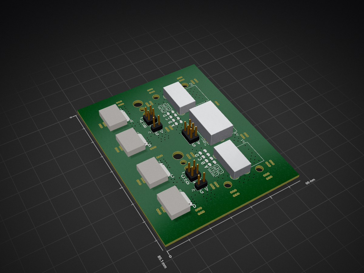
 sirkha/RPiUSBExt
Move the Pi's USB ports somewhere else using an Ethernet cable.
USB Extender is an open-source printed circuit board by sirkha, from the sirkha/RPiUSBExt repository on GitHub, published under the CC-BY-SA-4.0 licence. It is a 2-layer board of 66 × 85.1 mm with 60 parts on 26 nets, routed with 948 tracks and 311 vias.
(C) 2018 John C Kha
CC-BY-SA 4.0 - See License.text for more details
This board set provides two PCBs that plug into the USB ports on a Raspberry Pi and a board that connects to them via an RJ45 connection. Provisions for LEDs are provided.
Solder an ethernet cable (CAT 5, CAT 5e, CAT 6) to the two smaller boards and terminate the other end with an RJ45 connector. Provide power to the larger board and plug in the ethernet cable. Plug the two smaller boards into your Pi.
Links are examples, not endorsements.
Wire for connecting the LEDs and power is not included in the BOM. 20 AWG is recommended for power to prevent excessive voltage drop. Consider providing power seperately to the USB devices.
TODO: Write a detailed description
TODO
TODO
This project was inspired by and draws from work by Dustin Westaby.
| Qty | Value | Footprint | References |
|---|---|---|---|
| 4 | USB_A_PCB | parts:USB-A-PCB | J3, J4, J7, J8 |
| 2 | Conn_02x01 | Pin_Headers:Pin_Header_Straight_2x01_Pitch2.54mm | J1, J5 |
| 2 | Conn_02x02_Odd_Even | Pin_Headers:Pin_Header_Straight_2x02_Pitch2.54mm | J2, J6 |
| 2 | USB_A_Dual | parts:USB_A_DUAL | J11, J12 |
| 1 | Conn_02x03_Odd_Even | Pin_Headers:Pin_Header_Straight_2x03_Pitch2.54mm | J9 |
| 1 | RJ45_LEDS_SHIELD | RJ45-LED-Amphenol | J10 |
The 12 most common of 60 parts.


sd2psx/pcb
The PCB must be produced in 0.8mm thickness. Production files are provided under the "Releases" tab. These do not include the through-hole OLED module.


BitDogLab/BitDogLab
Open-source educational hardware for embedded systems, programming, electronics, and physical computing.
It measures 66 × 85.1 mm and has 2 copper layers, 1.6 mm thick.
60 parts. The full list of its parts is on this page, with links to each part's symbol and footprint where PCBKit's library has them.
From the sirkha/RPiUSBExt repository on GitHub, at the commit this page was made from: the board is USB Extender.kicad_pcb. PCBKit opens the board in the browser, with nothing to install.
Its repository publishes it under the CC-BY-SA-4.0 licence: you may reuse it on that licence's terms (keep the author's notice, and for a copyleft licence share your changes alike).