2 layers50 × 23.2 mm
Analog
hoglet67/RGBtoHDMI
Bare-metal Raspberry Pi project that provides pixel-perfect sampling of Retro Computer RGB/YUV video and conversion to HDMI
32 parts1kGPL-3.0

 sinara-hw/Kirdy_adapters
Thermal Interface Sheet P/N: RS PRO 245-7321
Kirdy LD adapter type 1 is an open-source printed circuit board by sinara-hw, from the sinara-hw/Kirdy_adapters repository on GitHub. It is a 2-layer board of 85 × 50 mm with 32 parts on 29 nets, routed with 180 tracks and 27 vias.
It is built around the M20-7870542. Its parts include 16 resistors, 5 connectors, 3 capacitors and 3 inductors. It belongs with the interfaces and adapters boards of this library.
Kirdy Adapter is a Butterfly Laser Diode Mount to be used with Kirdy mainboard.
User can run the following commands to export all the project output including Gerber & Drill files, Bill of Materials file, Schematics PDF and Step 3D model.
nix build .#LD_adapter_copper_platenix build .#LD_adapter_type_1_PCBnix build .#LD_adapter_type_2_PCBUser can fetch the correct KiCad Version used in the project by running the following command.
nix developUser can configure the following features by populating the corresponding jumper resistors:
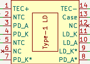
| Pin | Description |
|---|---|
| 1 | TEC+ |
| 2 | NTC |
| 3 | PD Anode |
| 4 | PD Cathode |
| 5 | NTC |
| 6 | Not Connected |
| 7 | PD Cathode* |
| 8 | PD Anode* |
| 9 | LD Cathode* |
| 10 | LD Anode |
| 11 | LD Cathode |
| 12 | Not Connected |
| 13 | LD Anode |
| 14 | TEC- |
*: Alternate LD/PD Connections.
User can configure the following features by populating the corresponding jumper resistors and capacitors:
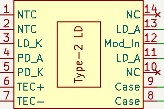
| Pin | Description |
|---|---|
| 1 | NTC |
| 2 | NTC |
| 3 | LD Cathode |
| 4 | PD Anode |
| 5 | PD Cathode |
| 6 | TEC+ |
| 7 | TEC- |
| 8 | Case (GND) |
| 9 | Case (GND) |
| 10 | Not Connected |
| 11 | LD Anode |
| 12 | Modulation Input |
| 13 | LD Anode |
| 14 | Not Connected |
It is preinstalled with a thermal interface sheet for ease of installation of laser diode. The thermal interface sheet preinstalled is subject to change.
Thermal Interface Sheet P/N: RS PRO 245-7321
| Qty | Value | Footprint | References |
|---|---|---|---|
| 14 | 0 | Resistor_SMD:R_0805_2012Metric | R1, R2, R3, R4, R5, R6, R7, R8, R9, R10, R12, R14, R15, R16 |
| 4 | M3 | laserSocket:78614110360_Receptacle | H1, H2, H3, H4 |
| 2 | 56n | Inductor_SMD:L_0402_1005Metric | L3, L4 |
| 2 | M20-7870542 | laserSocket:M20-7870542 | J1, J5 |
| 1 | 0 | Resistor_SMD:R_0402_1005Metric | R11 |
| 1 | 100p | Capacitor_SMD:C_0402_1005Metric | C2 |
| 1 | 10n | Capacitor_SMD:C_0402_1005Metric | C5 |
| 1 | 10n RF | Capacitor_SMD:C_0402_1005Metric | C3 |
| 1 | 132255-12 | Connector_Coaxial:SMA_Amphenol_132289_EdgeMount | J4 |
| 1 | 1u | Inductor_SMD:L_0805_2012Metric | L2 |
| 1 | 340 | Resistor_SMD:R_0402_1005Metric | R13 |
| 1 | Butterfly_Socket | laserSocket:Butterfly_Socket | J3 |
| 1 | kirdy | laserSocket:kirdy_socket | J2 |
| 1 | ~ | laserSocket:LD_Heat_Sink | Heat_Sink1 |
hoglet67/RGBtoHDMI
Bare-metal Raspberry Pi project that provides pixel-perfect sampling of Retro Computer RGB/YUV video and conversion to HDMI

hackclub/OnBoard
💡 Join 1,000 teenagers and make your first PCB with a $100 grant!


octosavvi/ESPKey
Wiegand data logger, replay device and micro door-controller

zmaker/arduino_cookbook
gli sketch del nuovo progetto Arduino Cookbook e dei video di YouTube

murexrobotics/electrical
Highly integrated electronics design and printed circuit boards (PCBs) for the MATE ROV Competition. Attempt the impossible.

swharden/AVR-projects
A collection of standalone AVR projects written in C

hardenedlinux/cheap-pcb
Cheap PCB: Better understanding the current status of hardware supply chain
It measures 85 × 50 mm and has 2 copper layers, 1.6 mm thick.
32 parts, built around the M20-7870542. The full list of its parts is on this page, with links to each part's symbol and footprint where PCBKit's library has them.
From the sinara-hw/Kirdy_adapters repository on GitHub, at the commit this page was made from: the board is kirdy_LD_adapter_type_1/kirdy_LD_adapter_type_1.kicad_pcb and its schematic kirdy_LD_adapter_type_1/kirdy_LD_adapter_type_1.kicad_sch. PCBKit opens the board in the browser, with nothing to install.
Its repository states no licence, so its author keeps all rights: ask sinara-hw before reusing the design.