2 layers19 × 76 mm
Sub
google/mozc-devices
Circuit diagrams and firmware source code for Gboard DIY keyboards
15 parts3kApache-2.0

 siddhipatel911/memory-game-pcb1
Custom ESP32-based memory game with KiCad PCB design - sponsored by PCBWay (simplified version of my Delirium Memory Game)
Memory game is an open-source printed circuit board by siddhipatel911, from the siddhipatel911/memory-game-pcb repository on GitHub, published under the MIT licence. It is a 2-layer board of 82.5 × 62.2 mm with 15 parts on 38 nets, routed with 20 tracks and 0 vias.
Its parts include 3 resistors, 3 diodes, 3 switches and 2 connectors.
A custom ESP32-based memory game built on a hand-designed PCB.
This is a learning project covering embedded firmware, schematic design, and PCB layout.
PCB prototype sponsored by PCBWay
| Stage | Status |
|---|---|
| Breadboard prototype | ✅ Complete |
| Hardware test firmware | ✅ Complete |
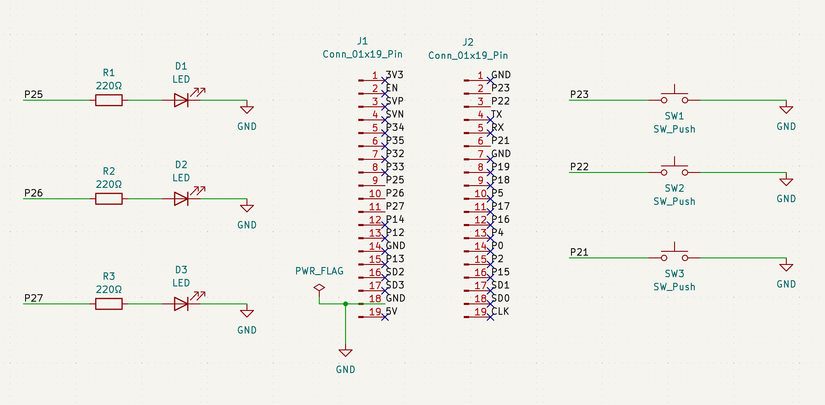
| KiCad schematic | ✅ Complete |
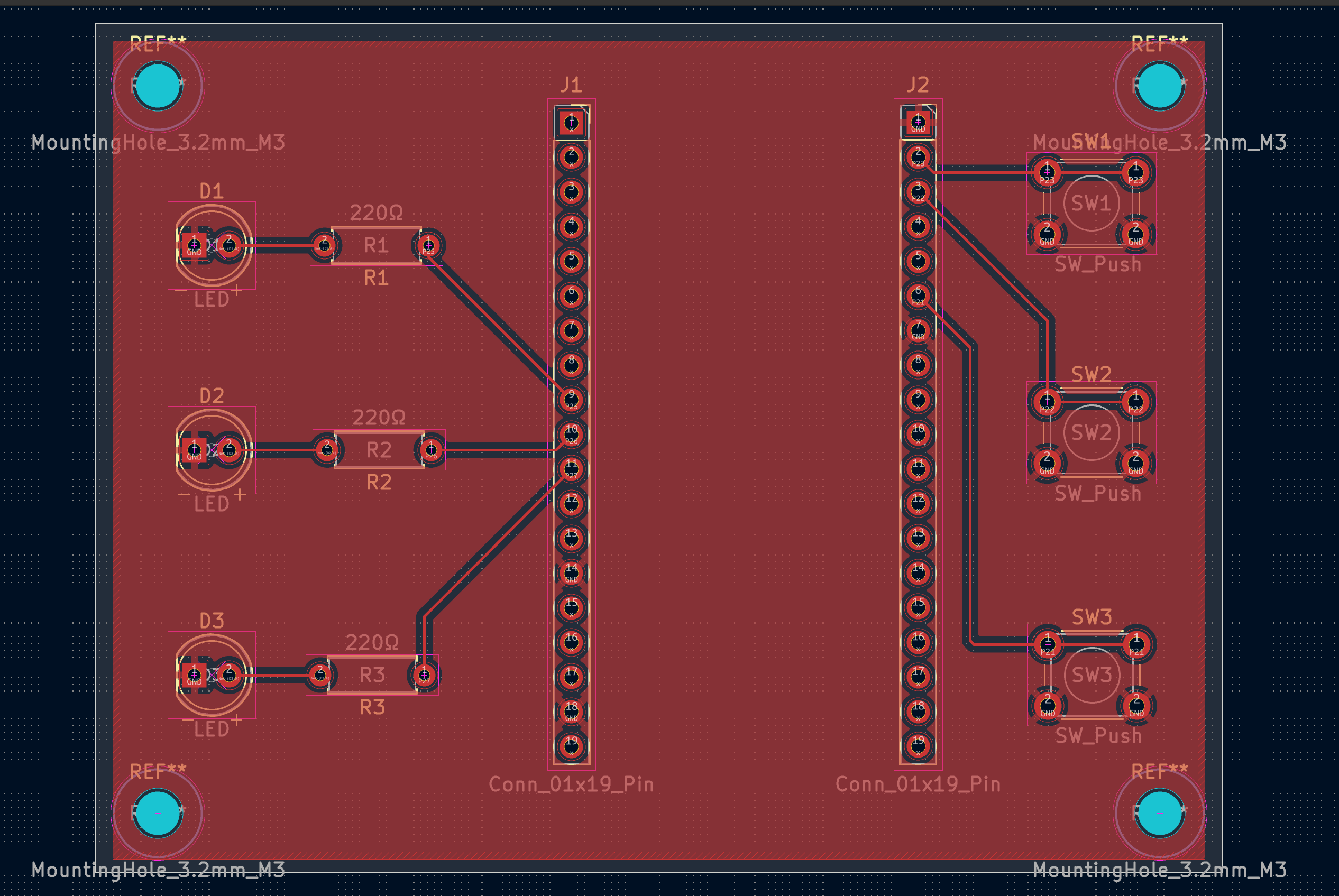
| PCB layout | ✅ Complete |
| PCB manufacturing (PCB Way) | ✅ Complete |
| PCB Assembly | 🔄 In progress |
| Final game logic firmware | ⏳ Planned |
This repository is a simplified hardware redesign of the original Delirium Memory Game project.
The original project focused on a more advanced RGB memory game system with expanded gameplay logic and additional hardware features.
This repository focuses specifically on:
Original project repository:
➡️ https://github.com/siddhipatel911/Delirium-Memory-Game
| Component | GPIO |
|---|---|
| SW1 | 23 |
| SW2 | 22 |
| SW3 | 21 |
| D1 | 25 |
| D2 | 26 |
| D3 | 27 |
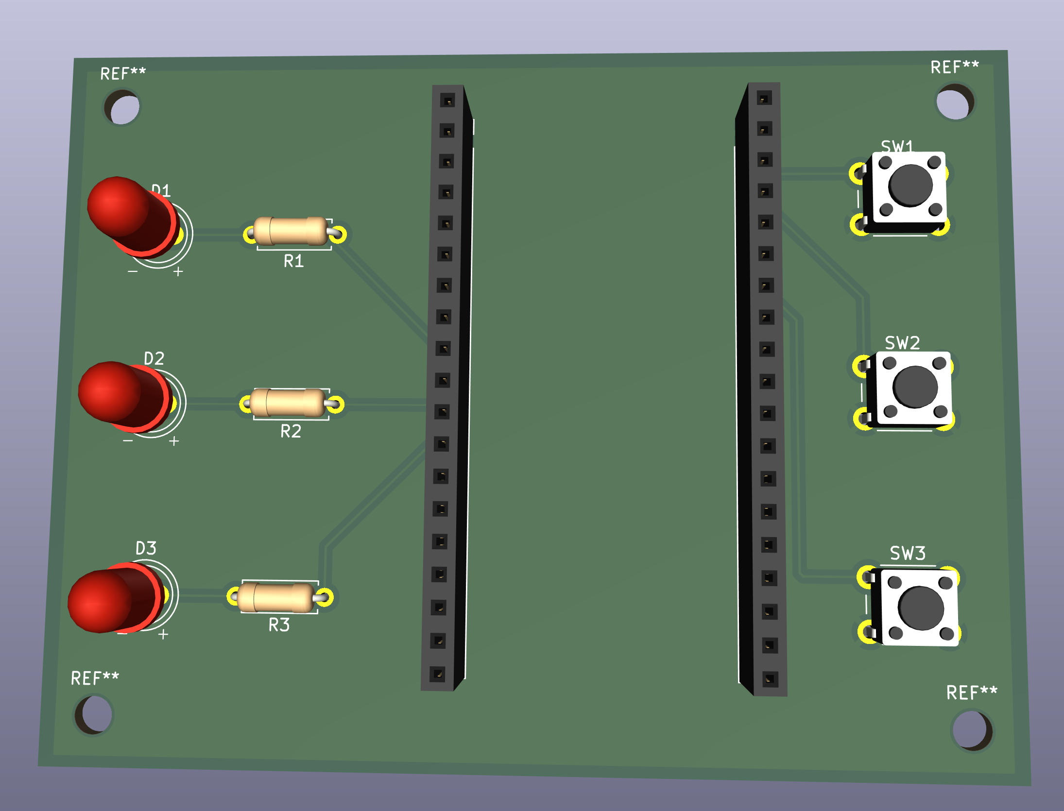
Designed in KiCad 10.0.0. 2-layer FR4 board, 82.5 × 62.2mm.
Initial hardware validation was done on a breadboard before PCB design.
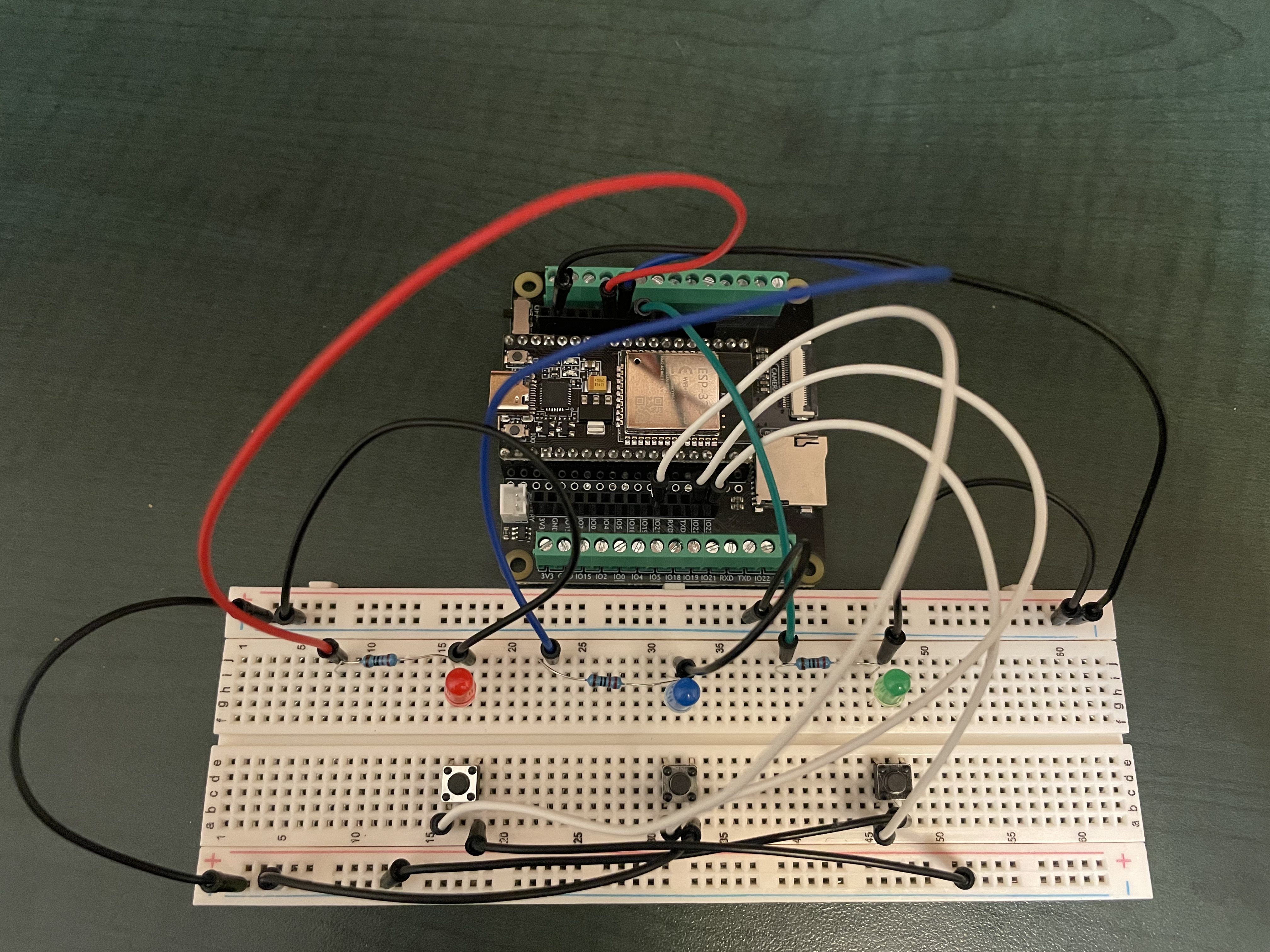
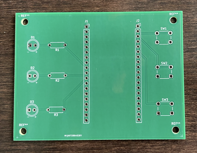
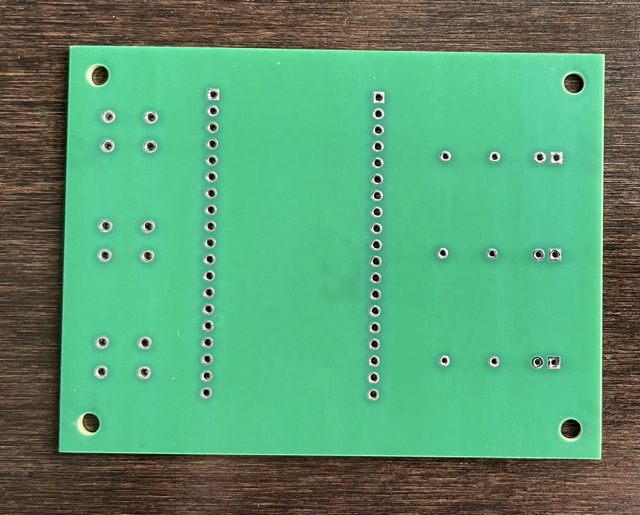
Located in memory_game/firmware/hardware_test/
Tests button inputs and LED outputs — each button lights its corresponding LED when pressed.
The final memory game firmware will be added to memory_game/firmware/game_logic/ after hardware is validated.
memory-game-pcb/
└── memory_game/
    ├── firmware/
    │   ├── hardware_test/     # Current test firmware
    │   └── game_logic/        # Final game firmware (coming soon)
    ├── hardware/
    │   ├── kicad/             # KiCad schematic and PCB files
    │   └── gerbers/           # Gerber files for manufacturing
    ├── docs/
    │   └── images/            # Project photos and renders
    └── bom/
        └── bom.md             # Bill of materials
PCB prototypes for this project are sponsored by PCBWay.
The ordering process was straightforward and easy to navigate, with clear communication throughout manufacturing and shipping. The boards were manufactured quickly, shipped promptly, and arrived well packaged with no visible damage.
Overall, the experience from placing the order to receiving the finished PCBs was smooth and professional.
Assembly and hardware validation are currently in progress. Once testing is complete, I'll update this section with a detailed review covering:
Based on my experience so far, PCBWay has provided a reliable and professional manufacturing service, and I appreciate their support of this open-source project.
MIT License — see LICENSE for details.
| Qty | Value | Footprint | References |
|---|---|---|---|
| 3 | 220Ω | Resistor_THT:R_Axial_DIN0207_L6.3mm_D2.5mm_P7.62mm_Horizontal | R1, R2, R3 |
| 3 | LED | LED_THT:LED_D5.0mm | D1, D2, D3 |
| 3 | SW_Push | Button_Switch_THT:SW_PUSH_6mm | SW1, SW2, SW3 |
| 2 | Conn_01x19_Pin | Connector_PinSocket_2.54mm:PinSocket_1x19_P2.54mm_Vertical | J1, J2 |
The 11 most common of 15 parts.
google/mozc-devices
Circuit diagrams and firmware source code for Gboard DIY keyboards

hoglet67/RGBtoHDMI
Bare-metal Raspberry Pi project that provides pixel-perfect sampling of Retro Computer RGB/YUV video and conversion to HDMI

mntmn/amiga2000-gfxcard
MNT VA2000, an Open Source Amiga 2/3/4000 Graphics Card (Zorro II/III), written in Verilog

hackclub/OnBoard
💡 Join 1,000 teenagers and make your first PCB with a $100 grant!

kenp-io/not-for-airpods-repairs
The content of this repository is licensed under the WTFPL License. Please have a close look at the terms before using this material.

Luos-io/luos_engine
Open-source and real-time orchestrator for cyber-physical-systems, to easily design, test and deploy embedded applications and digital twins.

Chrismettal/EleLab_v2
Cheap DIY lab system for hobbyists and the tinkering folk

It measures 82.5 × 62.2 mm and has 2 copper layers, 1.6 mm thick.
15 parts. The full list of its parts is on this page, with links to each part's symbol and footprint where PCBKit's library has them.
From the siddhipatel911/memory-game-pcb repository on GitHub, at the commit this page was made from: the board is memory_game/hardware/kicad/memory_game.kicad_pcb and its schematic memory_game/hardware/kicad/memory_game.kicad_sch. PCBKit opens the board in the browser, with nothing to install.
Its repository publishes it under the MIT licence: you may reuse it on that licence's terms (keep the author's notice, and for a copyleft licence share your changes alike).