


2 layers100 × 100 mm
Heatplate v1.1
DerSpatz/PCB-reflow-solder-heat-plate
hardware design for a PCB reflow solder heat plate
57 parts179MIT

 shlok-ac/Servo-Controller-5551
A 555 timer based servo controller designed in KiCad, including the schematic, PCB layout, 3D model, and fabrication files
Servo Controller-555 is an open-source printed circuit board by shlok-ac, from the shlok-ac/Servo-Controller-555 repository on GitHub, published under the CERN-OHL-S-2.0 licence. It is a 2-layer board of 60 × 50 mm with 20 parts on 12 nets, routed with 57 tracks and 1 via.
It is built around the AMS1117-5.0. Its parts include 4 resistors, 4 diodes, 3 capacitors, 2 ICs and 2 connectors. It belongs with the robots and motor control boards of this library.
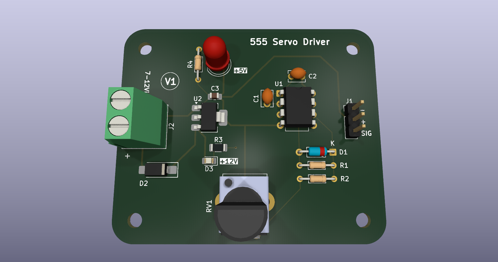
A 555 timer based servo controller designed in KiCad as part of my PCB design learning journey. The project focuses primarily on the PCB design workflow, including schematic and footprint selection, component placement, routing, 3D visualization, design-rule verification, and preparation of fabrication files.
Project status: PCB design completed. The board has not been physically manufactured or tested.



This project was created while working through the training modules by NU Teams.
The main goal was to practice the complete PCB design process in KiCad, including:
The underlying circuit uses a 555 timer to generate the control signal for a servo. A potentiometer is used to adjust the generated pulse, allowing the servo position to be varied. The circuit is kept relatively simple here because the primary focus of this repository is the PCB design and documentation workflow.
The PCB was designed with emphasis on:
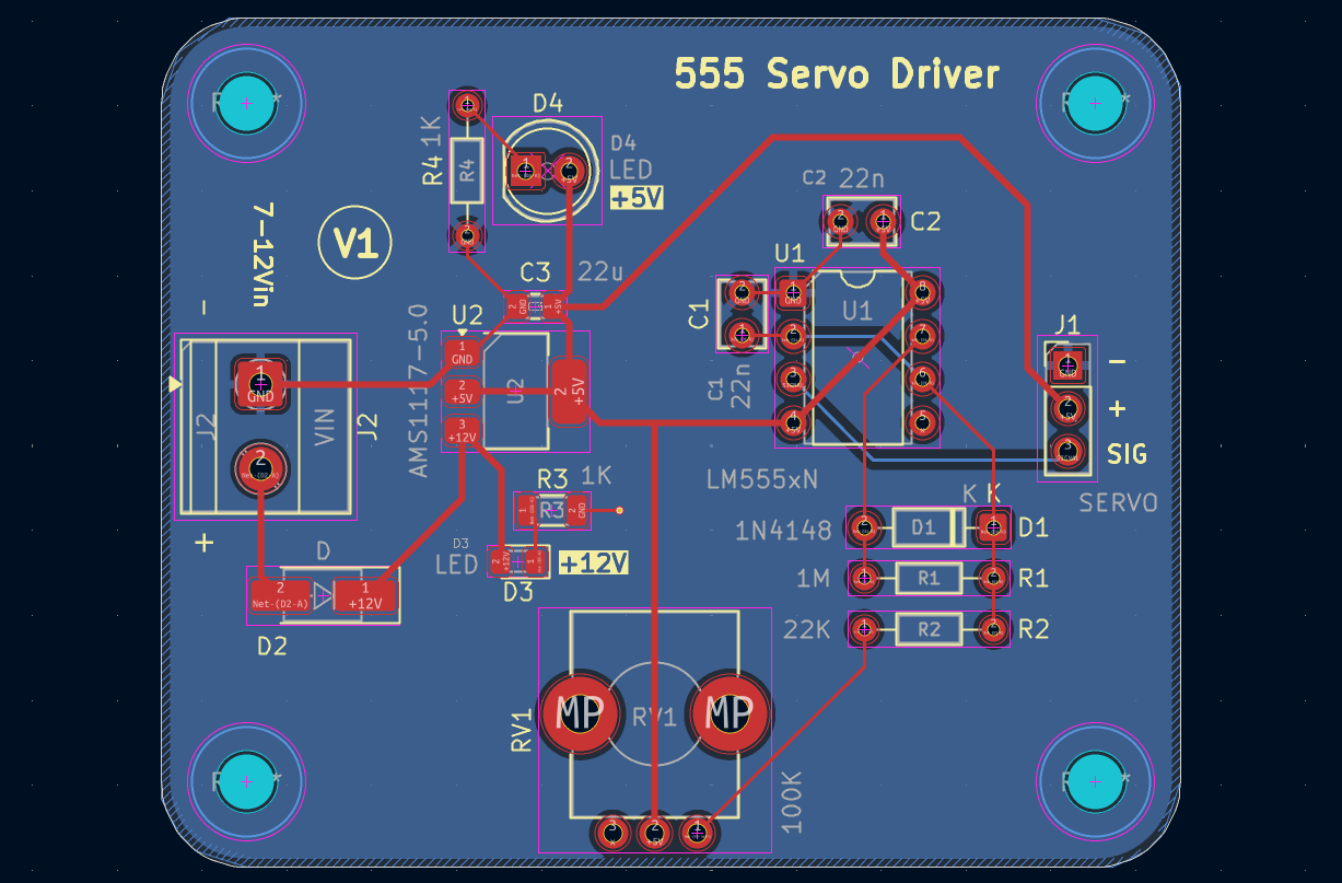
The project uses KiCad libraries and project-defined footprints for the components used on the PCB.
If the project is edited or reused, footprint assignments should be checked in the schematic and PCB files before making design changes.
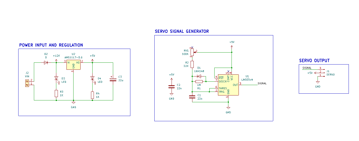
The circuit is based around a 555 timer configured to generate a servo control signal.
A potentiometer is used to vary the timing of the generated pulse, allowing the servo position to be adjusted.
The schematic is included primarily to document the electrical design associated with the PCB.
The design was checked using KiCad's Electrical Rules Checker (ERC) and Design Rules Checker (DRC).
These checks verify the design according to the configured KiCad rules. They do not replace physical testing of a manufactured PCB.
Although this PCB has not been physically manufactured, the repository contains the files generated during the design process for potential future fabrication and assembly.
PCB manufacturing files generated from the PCB layout.
Drill data generated for the PCB.
Component list generated from the KiCad project.
Component placement information generated from the PCB design.
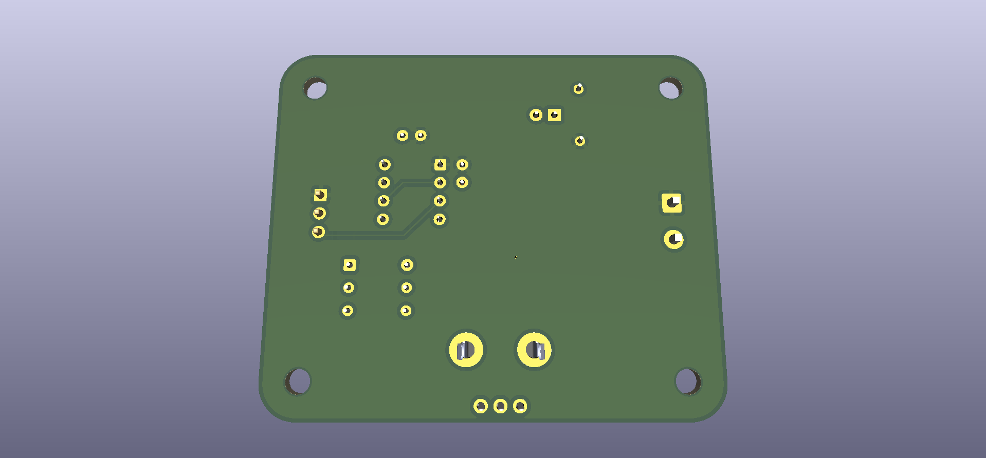
The PCB uses an external STEP model for component visualization in KiCad's 3D Viewer.
The model is stored separately from the KiCad project files:
external-cad/
└── Potentiometer_Bourns_PTV09A-1_Single_Vertical.step
The PCB references the model using a project-relative path, so the reference should remain valid when the repository is cloned to another system.
The redistribution rights of externally sourced CAD models depend on their original license/source. The external model is therefore treated separately from the project's own hardware design files.
This repository contains the complete KiCad project, including the schematic, PCB layout, project configuration, and supporting project assets.
To clone the project using Git:
git clone https://github.com/shlok-ac/Servo-Controller-555.git
cd Servo-Controller-555
Or use the GitHub repository page to download the project as a ZIP archive.
Servo Controller 555.kicad_pro in KiCad.The schematic, PCB layout, and project configuration files are kept together so that the project can be opened and edited as a complete KiCad project after cloning.
The main KiCad files are:
Servo Controller 555.kicad_pro — KiCad project configurationServo Controller 555.kicad_sch — schematicServo Controller 555.kicad_pcb — PCB layoutSee External CAD Models for the STEP model used by the PCB's 3D visualization.
This project was completed while working through the PCB Design Zero-to-Hero training modules by NU Teams.
The training material provided the learning framework for the project, while this repository contains my KiCad project files, PCB layout, documentation, verification results, and generated fabrication outputs.
Copyright © 2026 Shlok Chorge
This project is licensed under the CERN Open Hardware Licence Version 2 – Strongly Reciprocal (CERN-OHL-S-2.0).
This license allows others to:
Under the Strongly Reciprocal terms, modifications and derivative designs based on this project must be made available under the same license, along with the corresponding source design files.
See LICENSE for the complete license text.
Shlok Chorge · GitHub Profile
| Qty | Value | Footprint | References |
|---|---|---|---|
| 2 | 22n | Capacitor_THT:C_Disc_D3.8mm_W2.6mm_P2.50mm | C1, C2 |
| 1 | 100K | Potentiometer_THT:Potentiometer_Bourns_PTV09A-1_Single_Vertical | RV1 |
| 1 | 1K | Resistor_THT:R_Axial_DIN0204_L3.6mm_D1.6mm_P7.62mm_Horizontal | R4 |
| 1 | 1K | Resistor_SMD:R_1206_3216Metric | R3 |
| 1 | 1M | Resistor_THT:R_Axial_DIN0204_L3.6mm_D1.6mm_P7.62mm_Horizontal | R1 |
| 1 | 1N4148 | Diode_THT:D_DO-35_SOD27_P7.62mm_Horizontal | D1 |
| 1 | 22K | Resistor_THT:R_Axial_DIN0204_L3.6mm_D1.6mm_P7.62mm_Horizontal | R2 |
| 1 | 22u | Capacitor_SMD:C_0805_2012Metric_Pad1.18x1.45mm_HandSolder | C3 |
| 1 | AMS1117-5.0 | Package_TO_SOT_SMD:SOT-223-3_TabPin2 | U2 |
| 1 | D | Diode_SMD:D_SMA_Handsoldering | D2 |
| 1 | LED | LED_SMD:LED_0805_2012Metric_Pad1.15x1.40mm_HandSolder | D3 |
| 1 | LED | LED_THT:LED_D5.0mm | D4 |
| 1 | LM555xN | Package_DIP:DIP-8_W7.62mm | U1 |
| 1 | SERVO | Connector_PinHeader_2.54mm:PinHeader_1x03_P2.54mm_Vertical | J1 |
| 1 | VIN | TerminalBlock_Phoenix:TerminalBlock_Phoenix_MKDS-1,5-2_1x02_P5.00mm_Horizontal | J2 |
The 16 most common of 20 parts.
It measures 60 × 50 mm and has 2 copper layers, 1.6 mm thick.
20 parts, built around the AMS1117-5.0. The full list of its parts is on this page, with links to each part's symbol and footprint where PCBKit's library has them.
From the shlok-ac/Servo-Controller-555 repository on GitHub, at the commit this page was made from: the board is Servo Controller 555.kicad_pcb and its schematic Servo Controller 555.kicad_sch. PCBKit opens the board in the browser, with nothing to install.
Its repository publishes it under the CERN-OHL-S-2.0 licence: you may reuse it on that licence's terms (keep the author's notice, and for a copyleft licence share your changes alike).
DerSpatz/PCB-reflow-solder-heat-plate
hardware design for a PCB reflow solder heat plate

rheslip/2HPico-Eurorack-Module-Hardware
2HP Eurorack module based on Raspberry Pi Pico 2

victorhook/asac-fc
asac fc is an rp2040 based flight controller made for FPV drone flying


johannesstrueber/dots
DOTS eurorack module pcb schematics and code ATMega328 based


