2 layers99.7 × 99.7 mm

 shimo8810/rust-board
Hobby board implemented in Rust
Clock is an open-source printed circuit board by shimo8810, from the shimo8810/rust-board repository on GitHub, published under the MIT licence. It is a 2-layer board of 91.4 × 53.3 mm with 53 parts on 60 nets, routed with 411 tracks and 34 vias.
It is built around the ATTINY2313-20PU, 74HC165D and 74HC595, with the 2SC1815 among its other parts. Its parts include 27 resistors, 8 switches, 5 capacitors, 5 transistors and 3 ICs. It belongs with the lEDs and displays boards and the AVR (ATmega, ATtiny) boards of this library.


This project is intended for my personal study and information sharing. The main objectives are as follows:
Being a complete novice in circuit design, I created a simple hobby board for the purpose of studying circuit and PCB design.
The knowledge of developing embedded systems using Rust are scattered, so I wanted to compile information for myself. While there is a wealth of development information available for well-known boards, there is limited knowledge on directly controlling microcontrollers.
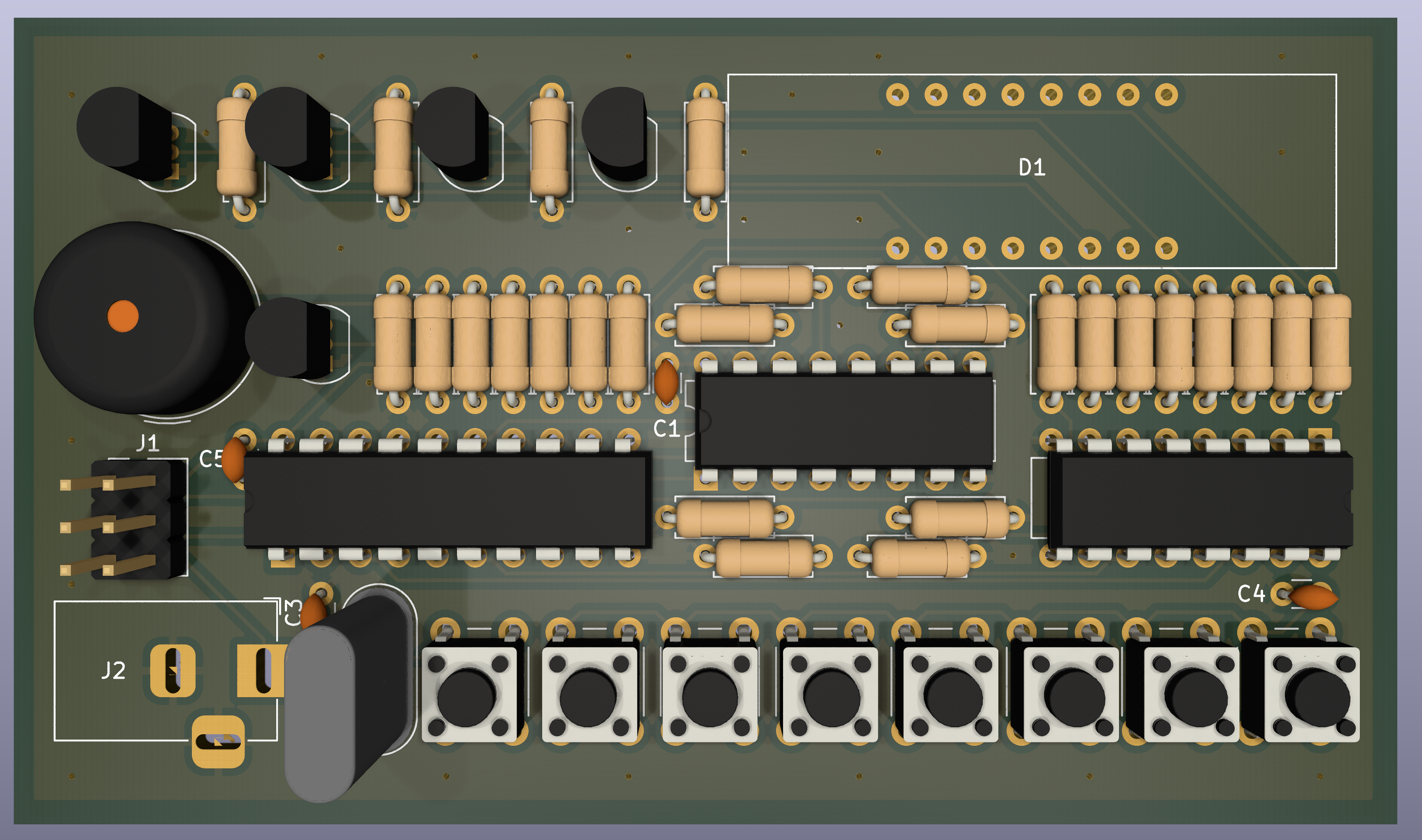
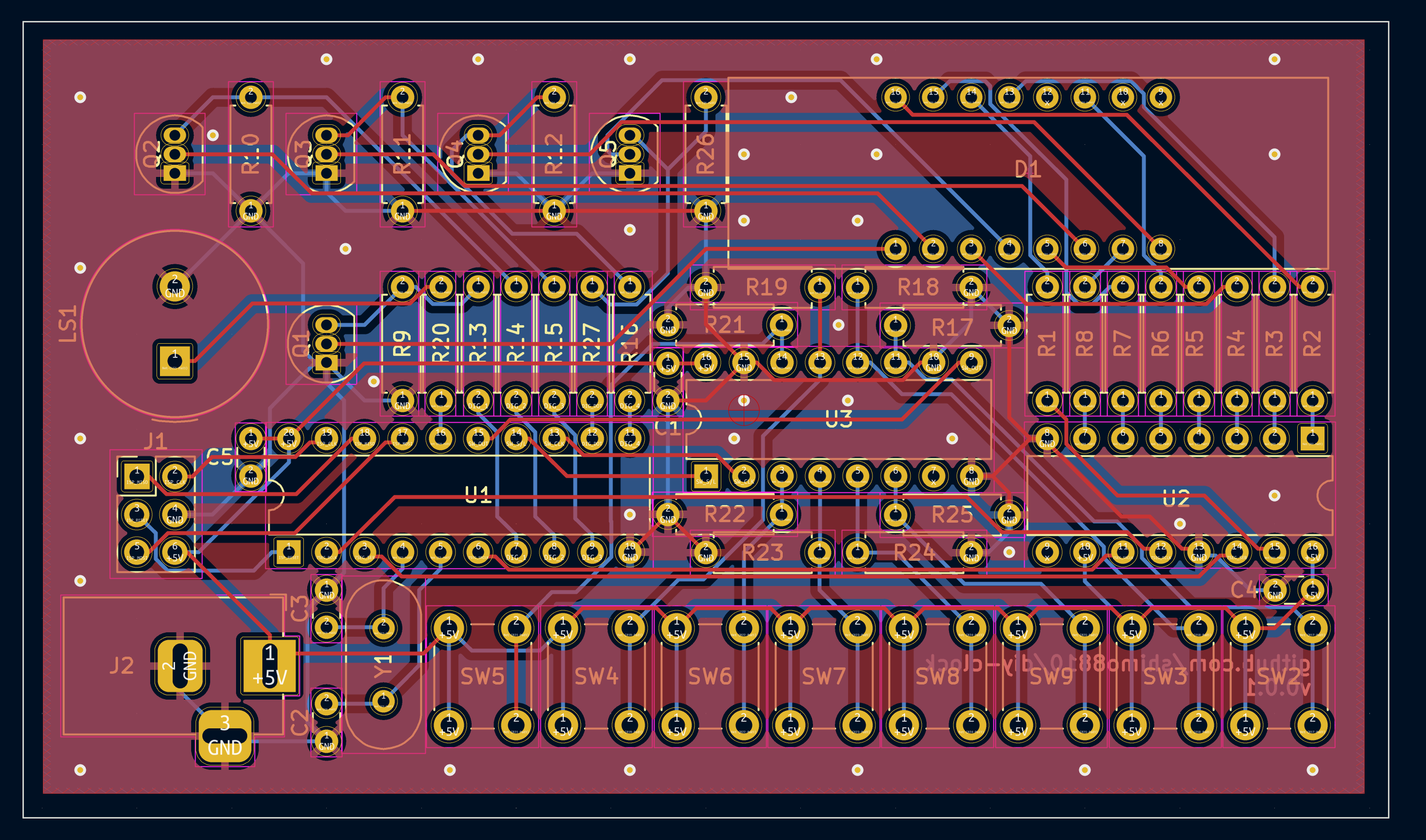
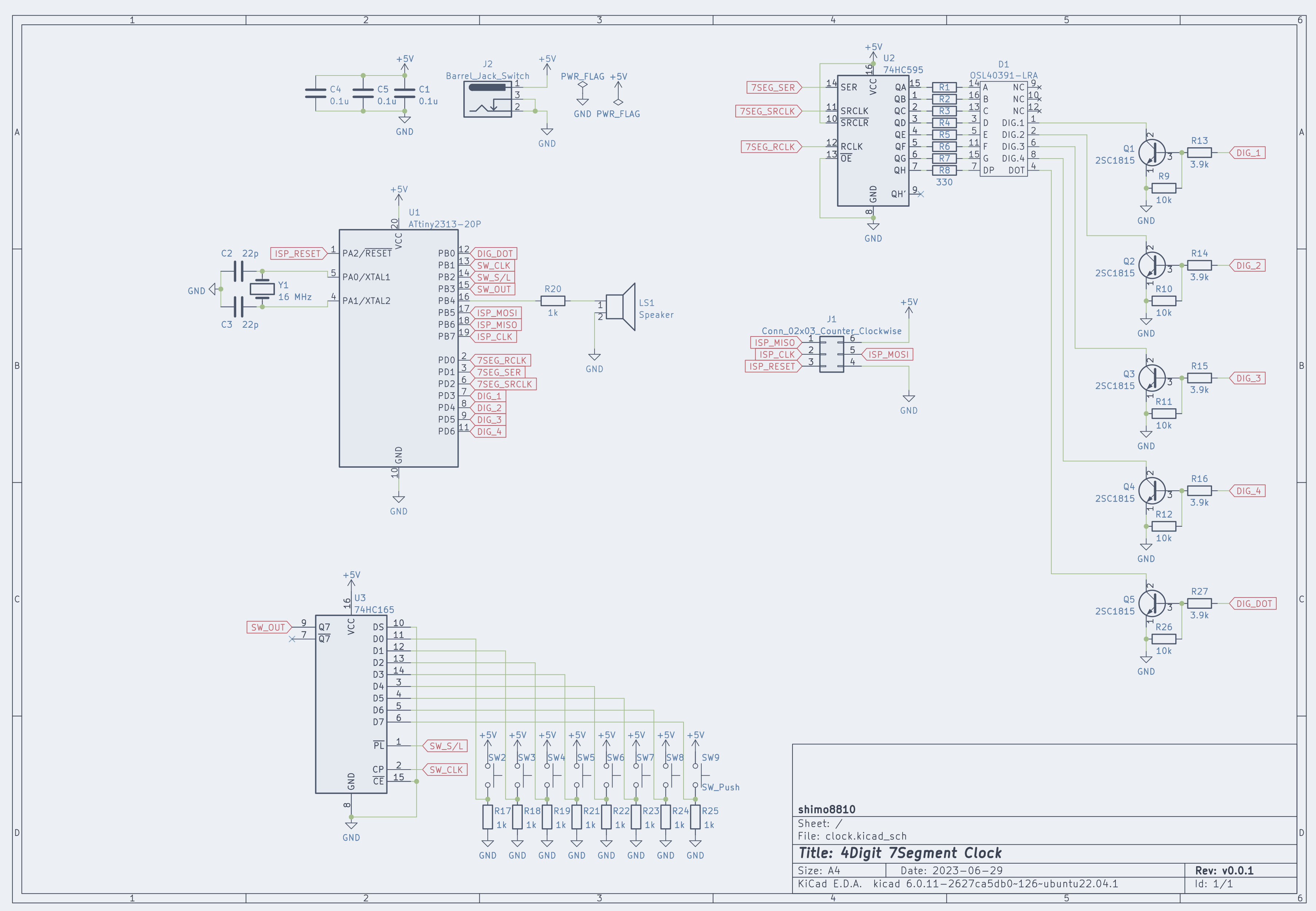
In this project, I use FT232RL to write firmware to this board. The connection between FT232RL and the clock's ISP pins should be made according to the table below. Please note that the current version has a design flaw in the ISP pin layout, which deviates from the standard ISP pin configuration. It has become confusing and inconvenient due to this misleading and unfortunate design. Therefore, caution should be exercised.
| FT232RL | PIN |
|---|---|
| CTS | ISP_MISO |
| DCD | ISP_MOSI |
| DSR | ISP_SCK |
| RI | ISP_RESET |
| VCC | 5V |
| GND | GND |
I use avrdude for writing the firmware. Writing can be performed with the following command. When writing for the first time, it is necessary to configure the fuse settings for attiny2313. Since we are running attiny2313 with an external oscillator (16MHz) and no prescaler, please write with the following settings.
avrdude -c diecimila \
        -p t2313 \
        -U flash:w:./target/avr-attiny2313/release/blink-attiny2313.elf:e \
-U lfuse:w:0xff:m| Qty | Value | Footprint | References |
|---|---|---|---|
| 9 | 1k | Resistor_THT:R_Axial_DIN0207_L6.3mm_D2.5mm_P7.62mm_Horizontal | R17, R18, R19, R20, R21, R22, R23, R24, R25 |
| 8 | 330 | Resistor_THT:R_Axial_DIN0207_L6.3mm_D2.5mm_P7.62mm_Horizontal | R1, R2, R3, R4, R5, R6, R7, R8 |
| 8 | SW_Push | Button_Switch_THT:SW_PUSH_6mm_H5mm | SW2, SW3, SW4, SW5, SW6, SW7, SW8, SW9 |
| 5 | 10k | Resistor_THT:R_Axial_DIN0207_L6.3mm_D2.5mm_P7.62mm_Horizontal | R9, R10, R11, R12, R26 |
| 5 | 2SC1815 | Package_TO_SOT_THT:TO-92_Inline | Q1, Q2, Q3, Q4, Q5 |
| 5 | 3.9k | Resistor_THT:R_Axial_DIN0207_L6.3mm_D2.5mm_P7.62mm_Horizontal | R13, R14, R15, R16, R27 |
| 3 | 0.1u | Capacitor_THT:C_Disc_D3.0mm_W1.6mm_P2.50mm | C1, C4, C5 |
| 2 | 22p | Capacitor_THT:C_Disc_D3.0mm_W1.6mm_P2.50mm | C2, C3 |
| 1 | 16 MHz | Crystal:Crystal_HC18-U_Vertical | Y1 |
| 1 | 74HC165 | Package_DIP:DIP-16_W7.62mm | U3 |
| 1 | 74HC595 | Package_DIP:DIP-16_W7.62mm | U2 |
| 1 | ATtiny2313-20P | Package_DIP:DIP-20_W7.62mm | U1 |
| 1 | Barrel_Jack_Switch | Connector_BarrelJack:BarrelJack_Horizontal | J2 |
| 1 | Conn_02x03_Counter_Clockwise | Connector_PinHeader_2.54mm:PinHeader_2x03_P2.54mm_Vertical | J1 |
| 1 | OSL40391-LRA | clock:OSL40391-LRA | D1 |
| 1 | Speaker | Buzzer_Beeper:Buzzer_TDK_PS1240P02BT_D12.2mm_H6.5mm | LS1 |
It measures 91.4 × 53.3 mm and has 2 copper layers, 1.6 mm thick.
53 parts, built around the ATTINY2313-20PU, 74HC165D, 74HC595 and 2SC1815. The full list of its parts is on this page, with links to each part's symbol and footprint where PCBKit's library has them.
From the shimo8810/rust-board repository on GitHub, at the commit this page was made from: the board is electronics/clock/clock.kicad_pcb and its schematic electronics/clock/clock.kicad_sch. PCBKit opens the board in the browser, with nothing to install.
Its repository publishes it under the MIT licence: you may reuse it on that licence's terms (keep the author's notice, and for a copyleft licence share your changes alike).


coprolitebbs/ps2-keyboard
Самодельная клавиатура с интерфейсом ps/2. Собрана на Attiny2313A и сдвиговых регистрах 74HC595 и 74HC165.