2 layers52 × 18.5 mm

 shilapi/ch341-to-mfi-chip150
A CH341F to MFI337S3959 board
Ch341-to mfi chip is an open-source printed circuit board by shilapi, from the shilapi/ch341-to-mfi-chip repository on GitHub. It is a 2-layer board of 23.5 × 18.4 mm with 14 parts on 12 nets, routed with 17 tracks and 1 via.
It is built around the CH341F, HR1117V-3.3 and MFI337S3959, with the USB-212-BCW among its other parts. Its parts include 5 capacitors, 4 resistors, 3 ICs and 1 connector.


A CH341F to MFI337/341/343 board.
Tested works.
Check release. Pick the one fits you best from releases and make it.
Usage: xcertplay

Some crazy SKUs.
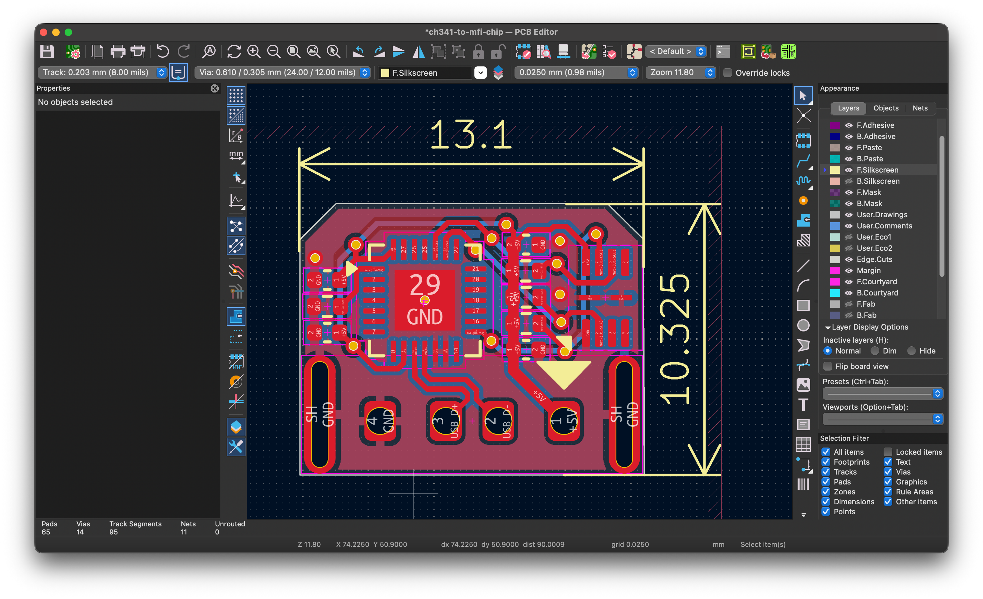 | 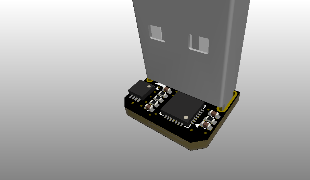 |
Check production for BOM and GERBER file.
| No. | Model | Qty |
|---|---|---|
| 1 | 10uF 0402 | 2 |
| 2 | 0.1uF 0402 | 3 |
| 3 | USB-212-BCW | 1 |
| 4 | 2kΩ 0402 | 1 |
| 5 | 2.2kΩ 0402 | 2 |
| 6 | 4.7kΩ 0402 | 1 |
| 7 | CH341F | 1 |
| 8 | HR1117V-3.3 | 1 |
| 9 | MFI337S3959 | 1 |
| Qty | Value | Footprint | References |
|---|---|---|---|
| 3 | 0.1uF | Capacitor_SMD:C_0402_1005Metric | C3, C4, C5 |
| 2 | 10uF | Capacitor_SMD:C_0402_1005Metric | C1, C2 |
| 2 | 2.2k | Resistor_SMD:R_0402_1005Metric | R2, R3 |
| 1 | 2k | Resistor_SMD:R_0402_1005Metric | R1 |
| 1 | 4.7k | Resistor_SMD:R_0402_1005Metric | R4 |
| 1 | CH341F | Package_DFN_QFN:QFN-28-1EP_4x4mm_P0.4mm_EP2.3x2.3mm | U1 |
| 1 | HR1117V-3.3 | Package_TO_SOT_SMD:SOT-89-3 | U2 |
| 1 | LOGO | KicadLibrary:GITHUB LOGO | G*** |
| 1 | MFI337S3959 | footprint:USON-8_2.5X2.5X0.5P | U3 |
| 1 | USB-212-BCW | footprint:917-511A1015B20200 | J1 |


google/mozc-devices
Circuit diagrams and firmware source code for Gboard DIY keyboards


hackclub/OnBoard
💡 Join 1,000 teenagers and make your first PCB with a $100 grant!


Twotoz/C5VRX
Ultra-minimal, zero-CPU 5.8 GHz analog FPV video receiver using ESP32-C5 Wi-Fi 6 PHY MODEM_DIAG, BitScrambler WBFM demodulation & resistor DAC CVBS
It measures 23.5 × 18.4 mm and has 2 copper layers, 1.6 mm thick.
14 parts, built around the CH341F, HR1117V-3.3, MFI337S3959 and USB-212-BCW. The full list of its parts is on this page, with links to each part's symbol and footprint where PCBKit's library has them.
From the shilapi/ch341-to-mfi-chip repository on GitHub, at the commit this page was made from: the board is USBA-3.3V-CH341-MFI337S3959/ch341-to-mfi-chip.kicad_pcb and its schematic USBA-3.3V-CH341-MFI337S3959/ch341-to-mfi-chip.kicad_sch. PCBKit opens the board in the browser, with nothing to install.
Its repository states no licence, so its author keeps all rights: ask shilapi before reusing the design.