2 layers200 × 66 mm

 shengwen-tw/nixie-clock9
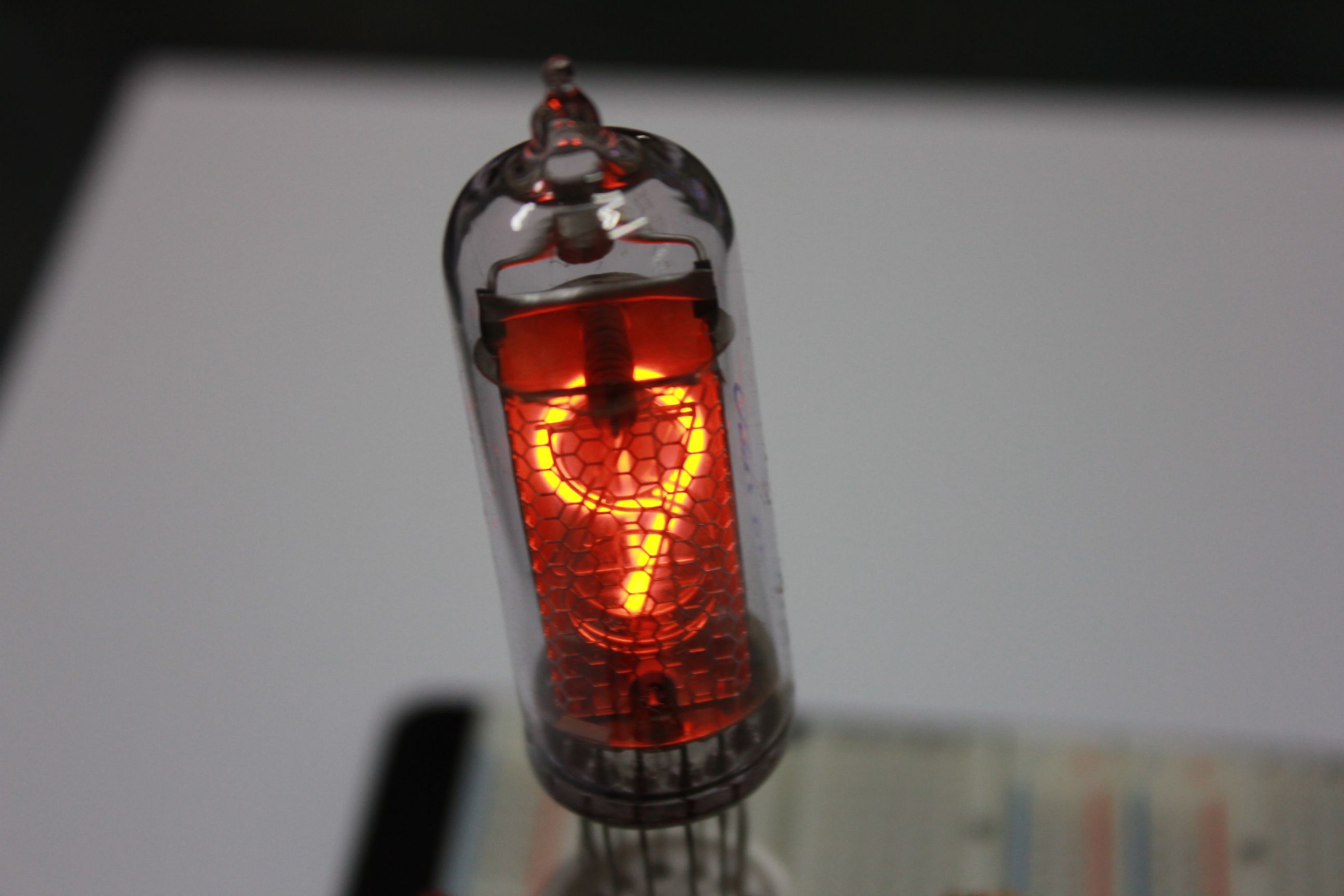
IN-14 Russian nixie tube clock
Nixie clock is an open-source printed circuit board by shengwen-tw, from the shengwen-tw/nixie-clock repository on GitHub, published under the MIT licence. It is a 2-layer board of 102.7 × 51.6 mm with 46 parts on 64 nets, routed with 851 tracks and 18 vias.
It is built around the ATMEGA328-PU, TLP521-4 and LM7805. Its parts include 12 resistors, 10 connectors, 8 ICs, 5 capacitors and 4 switches. It belongs with the lEDs and displays boards and the AVR (ATmega, ATtiny) boards of this library.


A Russian IN-14 Nixie tube clock which support time display, alram and mp3 playing function


You must install the following arduino libraries before compiling the firmware (find the zip in firmware directory)
Download Zadig
Select Options/List All Devices
Select USBasp
Select libusbK
Click Replace Driver
The hardware was designed under Kicad 4, any previous version may not work properly.
read the BOM.md for detailed information
| Qty | Value | Footprint | References |
|---|---|---|---|
| 6 | 330ohm | R1 | R2, R3, R4, R5, R6, R7 |
| 6 | CONN_2 | PIN_ARRAY_2X1 | P1, P2, P7, P8, P9, P10 |
| 4 | TLP521 | DIP-8__300_ELL | U2, U3, U4, U7 |
| 3 | NPN | TO92 | Q1, Q2, Q3 |
| 3 | SW_PUSH | PIN_ARRAY_2X1 | SW1, SW2, SW3 |
| 2 | 0.1 uf | C1 | C2, C3 |
| 2 | 1.8kohm | R1 | R11, R12 |
| 2 | 22pf | C1 | C4, C5 |
| 2 | 4.7k ohm | R1 | R8, R9 |
| 2 | CONN_4 | PIN_ARRAY_4x1 | P3, P4 |
| 2 | P*** | Connect:1pin | 1PIN, 1PIN |
| 1 | 100 uf | C1V7 | C1 |
| 1 | 100k ohm | R1 | R1 |
| 1 | 10k ohm | R1 | R10 |
| 1 | 16MHZ | HC-49V | X1 |
| 1 | ATMEGA328-P | DIP-28__300_ELL | IC1 |
| 1 | CONN_12 | pin_array_6x2 | P6 |
| 1 | CONN_8 | pin_array_4x2 | P5 |
| 1 | HEF42028 | DIP-16__300_ELL | U5 |
| 1 | K155ID1 | DIP-16__300_ELL | U6 |
| 1 | LM7805 | LM78XX | U1 |
| 1 | SW_PUSH | SW_PUSH_SMALL | SW4 |
| 1 | VAL** | OSHW_COPPER_10MM | OSHW_COPPER_10MM |


Squantor/DiySolderingStation
Do it yourself soldering station

m24h/espcnc
A 3D printer/CNC controller using ESP32 with its DMA/FIFO bufferd I2S port

nanjava82/headboard_hardware
KiCad에서 headerboard/headerboard.kicadpro를 열면 프로젝트를 사용할 수 있습니다. 기존 작업 환경은 KiCad 7.0.6입니다.


QuintusJoyal/avr-irremote-led-lamp
the signals on the bus go blink, blink, blink

arvjus/Extended_RC6502_Apple1
Flash Disk Storage for RC6502 Apple1 Replica
It measures 102.7 × 51.6 mm and has 2 copper layers, 1.6 mm thick.
46 parts, built around the ATMEGA328-PU, TLP521-4 and LM7805. The full list of its parts is on this page, with links to each part's symbol and footprint where PCBKit's library has them.
From the shengwen-tw/nixie-clock repository on GitHub, at the commit this page was made from: the board is circuit/prototype_ver1/control_board/nixie-clock.kicad_pcb. PCBKit opens the board in the browser, with nothing to install.
Its repository publishes it under the MIT licence: you may reuse it on that licence's terms (keep the author's notice, and for a copyleft licence share your changes alike).