2 layers20.5 × 24.8 mm

 sheffieldhackspace/bay-indicator
An Adafruit GFX compatible driver for the AS1100 bus station dot matrix display.
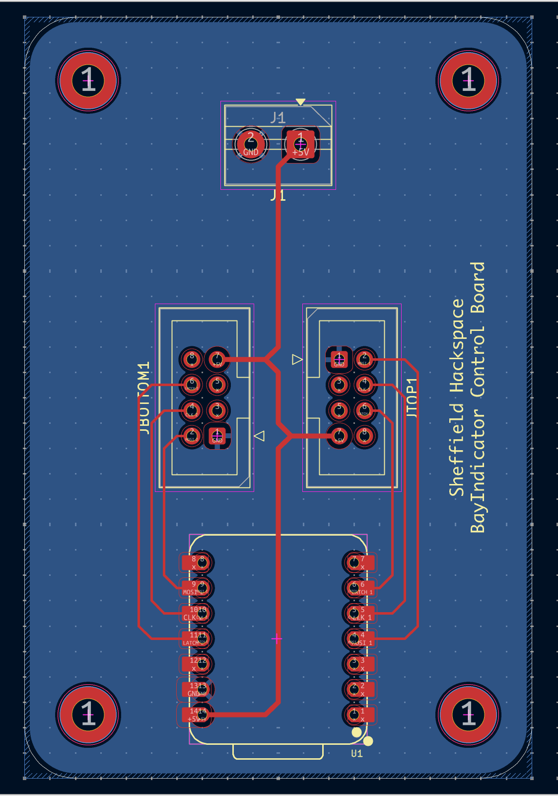
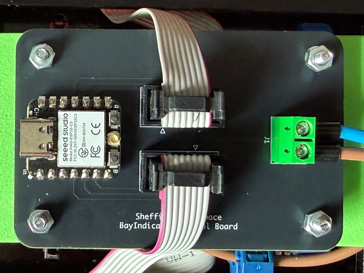
Bay indicator is an open-source printed circuit board by sheffieldhackspace, from the sheffieldhackspace/bay-indicator repository on GitHub, published under the MIT licence. It is a 2-layer board of 50.8 × 76.2 mm with 8 parts on 26 nets, routed with 42 tracks and 0 vias.
Its parts include 1 IC and 1 connector. It belongs with the lEDs and displays boards and the ESP32 and RISC-V boards of this library.
An Adafruit GFX compatible driver for the Infotec bay indicator AS1100-based dot matrix display.
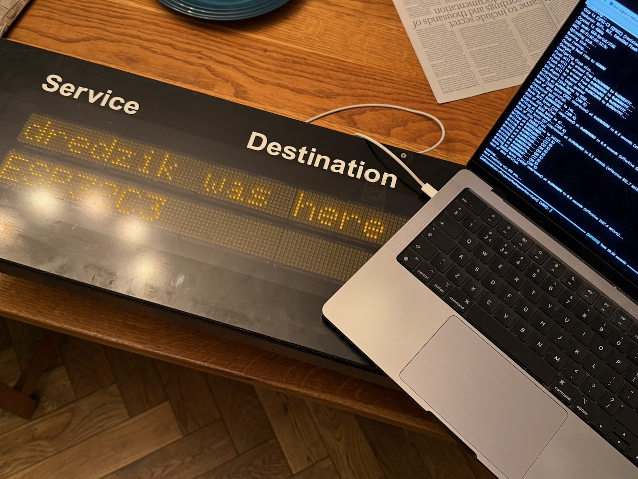
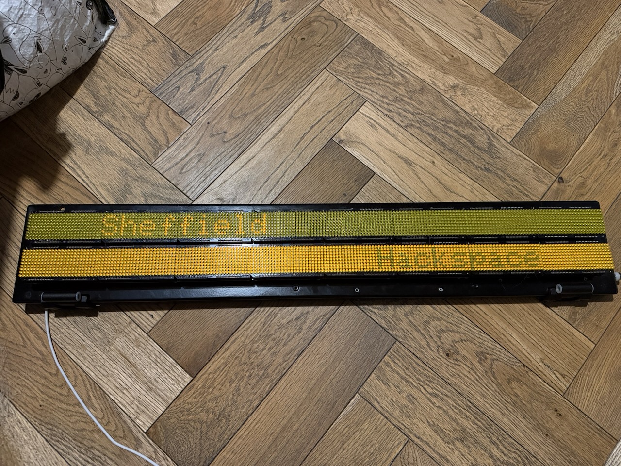
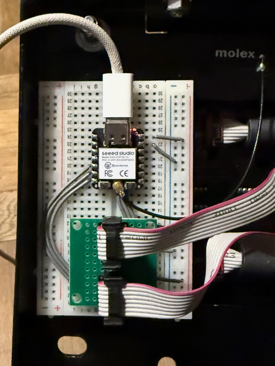
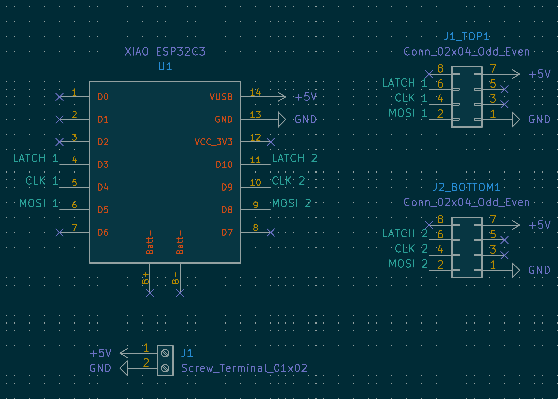
See the KiCad project for the full schematic.
Add the following to your platformio.ini:
lib_deps =
    adafruit/Adafruit BusIO
    adafruit/Adafruit GFX Library
https://github.com/sheffieldhackspace/display-infotec-bay-indicator#include <BayIndicator.h>
BayIndicator display1 = BayIndicator(D5, D6, D4);
BayIndicator display2 = BayIndicator(D8, D7, D9);
void setup() {
delay(1000); // Give the display a moment to power up before configuring it
display1.begin();
display1.fillScreen(0);
display1.setCursor(1, 1);
display1.print("Sheffield");
display1.display();
display2.begin();
display2.fillScreen(0);
display2.setCursor(1, 1);
display2.print("Hackspace");
display2.display();
}
void loop() {
// update displays as needed
display1.display();
display2.display();
}Since BayIndicator inherits from GFXcanvas1, the full
Adafruit GFX API
is available for drawing text, shapes, and bitmaps. Call display.display()
to flush the canvas to the hardware.
Three examples are included in the examples/ directory. To build and flash them, clone the repository and run:
# Show a hardware test pattern
pio run -t upload -e test

# Show a checkerboard pattern
pio run -t upload -e checkerboard

# Scroll two lines of text around the display
pio run -t upload -e movingwordsInspired by the works of alifeee and
ConnectedHumber.
The reverse engineering work of the display's segment layout and SPI protocol
was instrumental in the development of this library.
| Qty | Value | Footprint | References |
|---|---|---|---|
| 2 | Conn_02x04_Odd_Even | Connector_IDC:IDC-Header_2x04_P2.54mm_Vertical | JBOTTOM1, JTOP1 |
| 1 | Screw_Terminal_01x02 | TerminalBlock:TerminalBlock_MaiXu_MX126-5.0-02P_1x02_P5.00mm | J1 |
| 1 | XIAO ESP32C3 | kicad-footprints:XIAO Seeed ESP32C3 DIP | U1 |
The 4 most common of 8 parts.
It measures 50.8 × 76.2 mm and has 2 copper layers, 1.6 mm thick.
8 parts. The full list of its parts is on this page, with links to each part's symbol and footprint where PCBKit's library has them.
From the sheffieldhackspace/bay-indicator repository on GitHub, at the commit this page was made from: the board is kicad/BayIndicator.kicad_pcb and its schematic kicad/BayIndicator.kicad_sch. PCBKit opens the board in the browser, with nothing to install.
Its repository publishes it under the MIT licence: you may reuse it on that licence's terms (keep the author's notice, and for a copyleft licence share your changes alike).

joeycastillo/Sensor-Watch
A board replacement for the classic Casio F-91W wristwatch

rusefi/rusefi
rusefi - GPL internal combustion engine control unit

hoglet67/RGBtoHDMI
Bare-metal Raspberry Pi project that provides pixel-perfect sampling of Retro Computer RGB/YUV video and conversion to HDMI

shanteacontrols/OpenDeck
A platform for building interactive control and sensing devices using MIDI and OSC built with Zephyr RTOS.

hackclub/OnBoard
💡 Join 1,000 teenagers and make your first PCB with a $100 grant!

dangiu/PicoMemcard
Emulating PSX Memory Card (or controller) using a Raspberry Pi Pico

OLIMEX/DIY-LAPTOP
Do It Yourself Open Source Hardware and Software Modular Hacker's Friendly Laptop