
2 layers22.2 × 46.4 mm
C64-Switchless Quad Kernal Switcher
bwack/C64-Switchless-Multi-Kernal-27C256-adapter
Kernal switcher for the C64/C64C/C128
14 parts112

 sheelis/cnc-spindle-light1
Mount and PCB for CNC spindle to illuminate the tool from all sides in any color or sequence.
Z top pcb is an open-source printed circuit board by sheelis, from the sheelis/cnc-spindle-light repository on GitHub, published under the GPL-3.0 licence. It is a 2-layer board of 47.8 × 37.8 mm with 18 parts on 17 nets, routed with 76 tracks and 0 vias.
It is built around the ATTINY85-20PU. Its parts include 8 connectors, 2 resistors, 2 switches, 1 IC and 1 diode. It belongs with the robots and motor control boards and the AVR (ATmega, ATtiny) boards of this library.
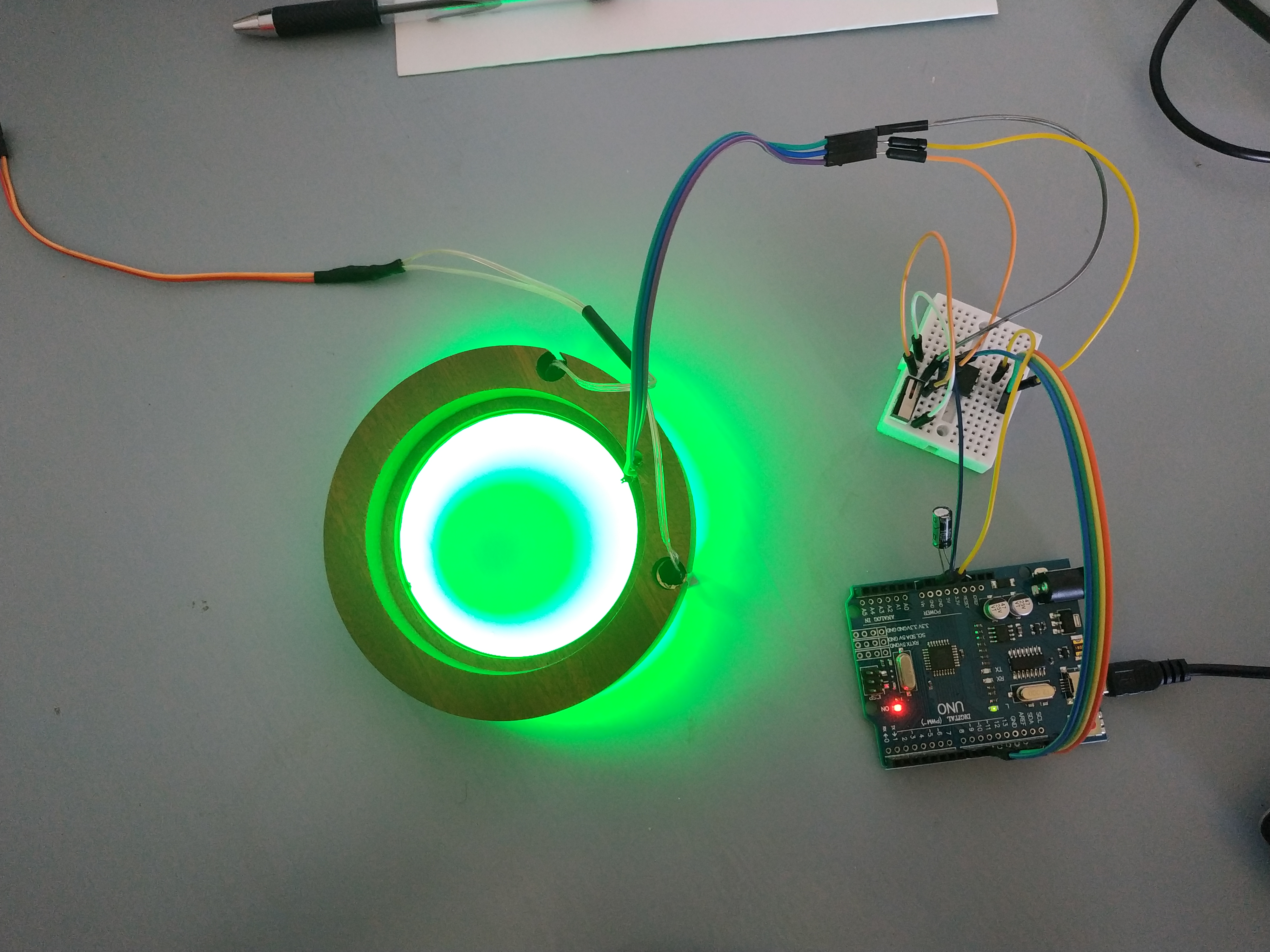
This is a PCB and spindle attachment design and software to light up the CNC work area from all sides in any color or sequence desired (as long as you can program it to). The LED control is done by FastLED library, so it's not too hard to create your own sequences.
There is also an option to insert 2 lasers at 90* difference from each other in order to produce a cross shape on XY plane exactly where the tool will touch the work piece. Lasers have their own connectors and on/off switch on the PCB. There is also a provision for attaching the the Z probe to the pcb, but it is only tested on my own DIY CNC.
You will find here:
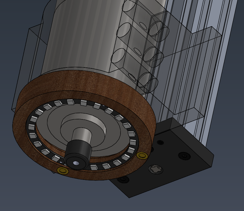
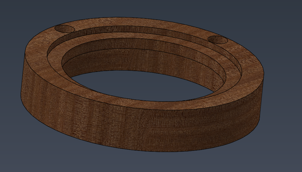
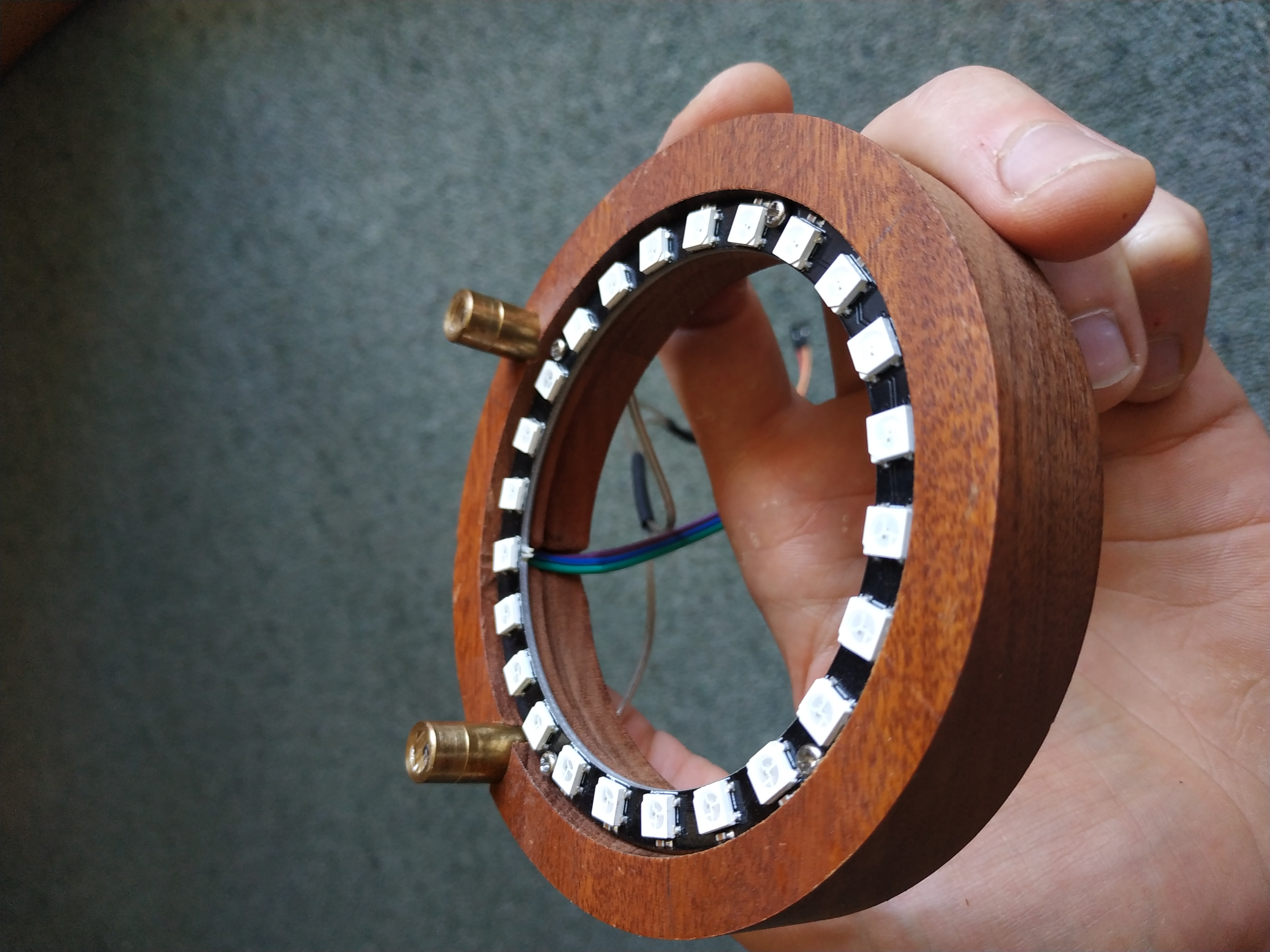
Then milled the wooden mount and attached the LED ring and lasers. I did not insert the lasers fully because later i will need to rotate them to align with center.
The mounting holes on the PCB align with any 20mm increment profiles such as my 2080 C-beam
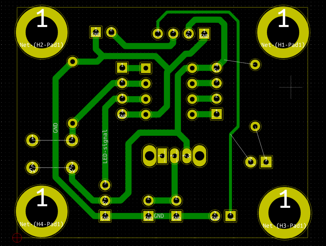
PCB milled with a 0.2mm HSS bit
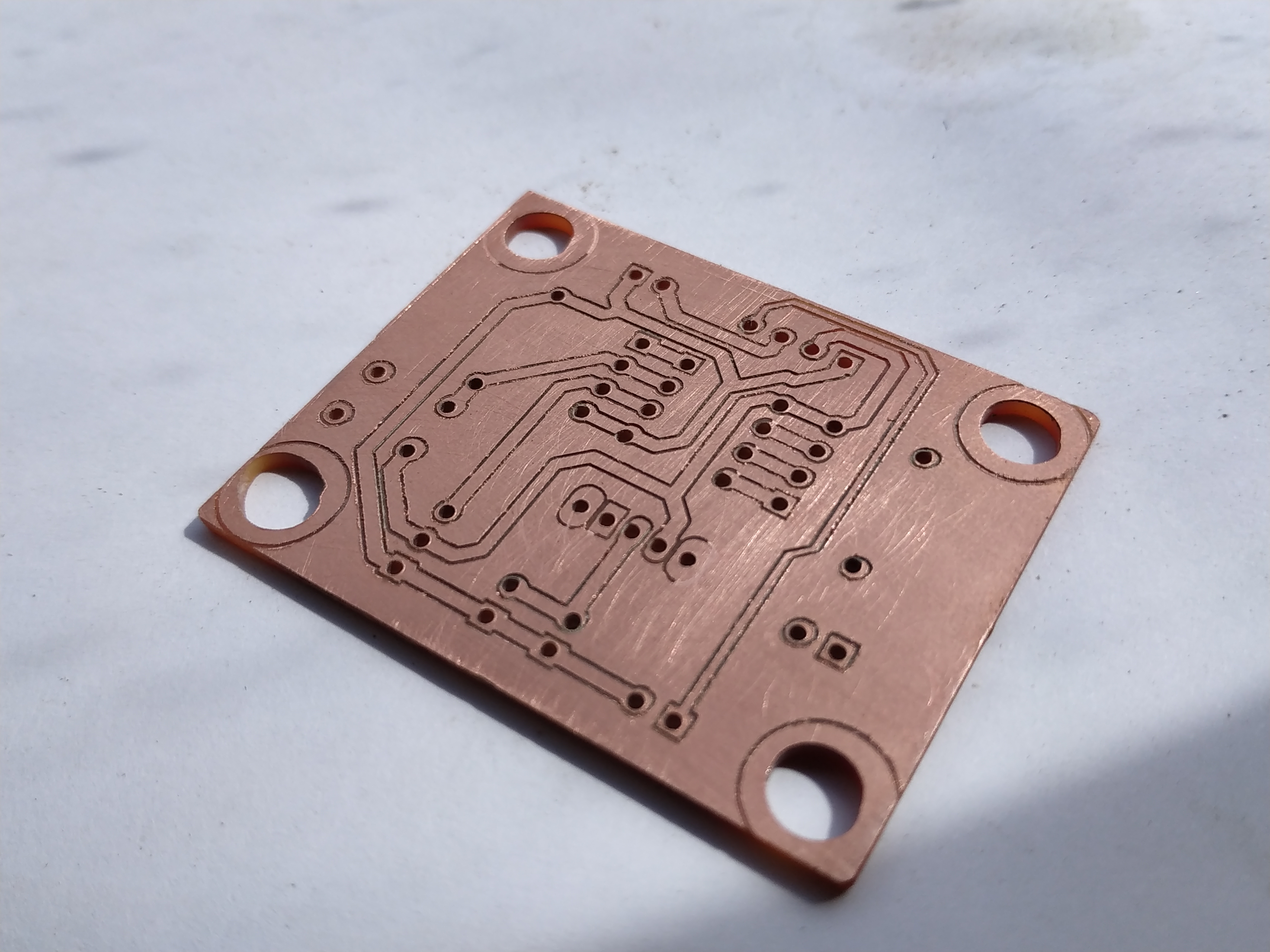
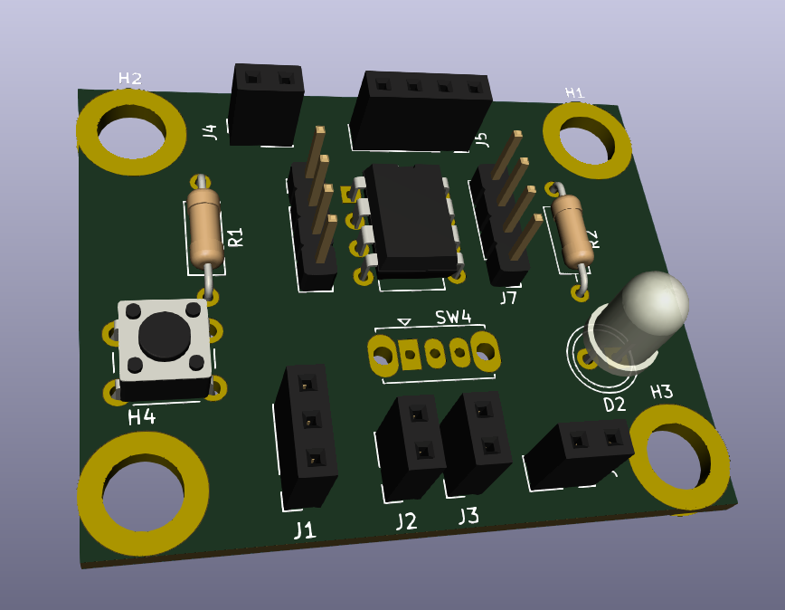
And the assembled PCB
This project requires:
PM me for questions and comments!
| Qty | Value | Footprint | References |
|---|---|---|---|
| 4 | h | MountingHole:MountingHole_5.3mm_M5_ISO14580_Pad | H1, H2, H3, H4 |
| 2 | 10k | Resistor_THT:R_Axial_DIN0207_L6.3mm_D2.5mm_P10.16mm_Horizontal | R1, R2 |
| 2 | tiny-conn | Connector_PinHeader_2.54mm:PinHeader_1x04_P2.54mm_Vertical | J7, J8 |
| 1 | ATtiny85-20PU | Package_DIP:DIP-8_W7.62mm | U1 |
| 1 | FAN | Connector_PinSocket_2.54mm:PinSocket_1x02_P2.54mm_Vertical | J4 |
| 1 | INPUT | Connector_PinSocket_2.54mm:PinSocket_1x04_P2.54mm_Vertical | J5 |
| 1 | L1 | Connector_PinSocket_2.54mm:PinSocket_1x02_P2.54mm_Vertical | J2 |
| 1 | L2 | Connector_PinSocket_2.54mm:PinSocket_1x02_P2.54mm_Vertical | J3 |
| 1 | LED-MODE | Button_Switch_THT:SW_PUSH_6mm | SW1 |
| 1 | LEDS | Connector_PinSocket_2.54mm:PinSocket_1x03_P2.54mm_Vertical | J1 |
| 1 | PROBE | Connector_PinSocket_2.54mm:PinSocket_1x02_P2.54mm_Vertical | J6 |
| 1 | PROBE LED | LED_THT:LED_D5.0mm_Clear | D2 |
| 1 | X | Button_Switch_THT:SW_Slide_1P2T_CK_OS102011MS2Q | SW4 |
It measures 47.8 × 37.8 mm and has 2 copper layers, 1.6 mm thick.
18 parts, built around the ATTINY85-20PU. The full list of its parts is on this page, with links to each part's symbol and footprint where PCBKit's library has them.
From the sheelis/cnc-spindle-light repository on GitHub, at the commit this page was made from: the board is kicad-files/z-top-pcb.kicad_pcb. PCBKit opens the board in the browser, with nothing to install.
Its repository publishes it under the GPL-3.0 licence: you may reuse it on that licence's terms (keep the author's notice, and for a copyleft licence share your changes alike).
bwack/C64-Switchless-Multi-Kernal-27C256-adapter
Kernal switcher for the C64/C64C/C128

plusvic/simplebus2-intercom
General description of the Simplebus2 protocol used by some Comelit's intercoms. Hardware for retransmitting Simplebus2 messages over UART.

osmocom/osmocom-analog
Software Implementation of analog cellular telephony systems like NMT, TACS, IMTS, A/B/C-Netz; mirror of https://gitea.osmocom.org/cellular-infrastructure/osmocom-analog

strickyak/jerboa-attiny85-mod-synth
Modular Synthesizer using an ATtiny85 chip for each module.


Hack-a-Day/Remoticon_KiCad_Blender
support files for the 2020 Remoticon KiCad to Blender > PCB renders workshop
