2 layers103 × 30.5 mm
 shaxa484/CodePad
My first attempt at making hardware
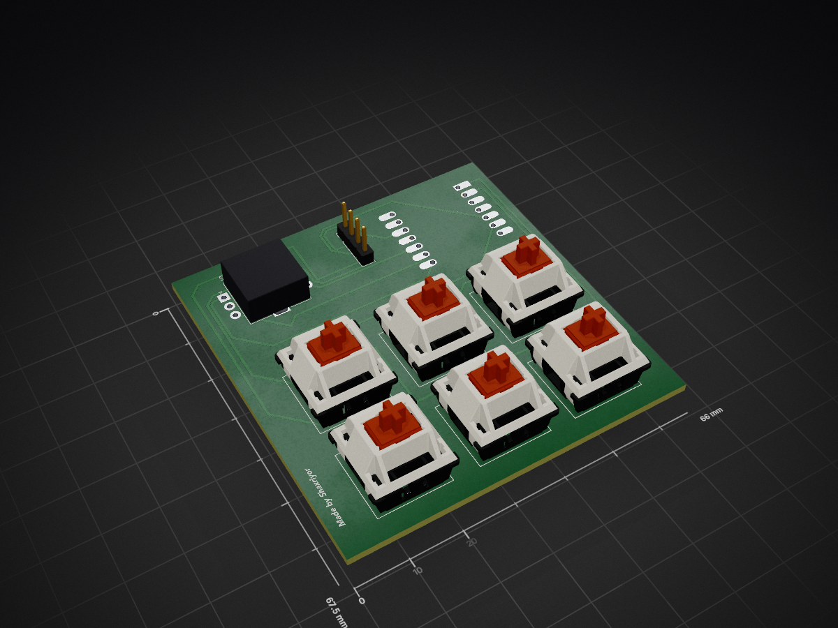
My lefty hackpad is an open-source printed circuit board by shaxa484, from the shaxa484/CodePad repository on GitHub, published under the MIT licence. It is a 2-layer board of 66 × 67.5 mm with 9 parts on 14 nets, routed with 140 tracks and 0 vias.
Its parts include 7 switches, 1 IC and 1 connector. It belongs with the keyboards and input boards of this library.
CodePad is a 6 key macropad with a rotary encoder, and an OLED Display made for helping me while coding. It uses QMK firmware.
Everything fits together using 4 M3 Bolts and heatset inserts. 4 for the each corner of the case.
It has 2 separate printed pieces. The base where the PCB sits, and the top cover.
<img src=assets/cad.jpg alt="Schematic" width="500"/>
Made in Fusion360.
Here's my PCB! It was made in KiCad.
Schematic <img src=assets/schematic.jpg alt="Schematic" width="300"/>
PCB <img src=assets/pcb.jpg alt="Schematic" width="300"/>
I opted for direct GPIO connections rather than a switch matrix. Given the small number of keys (6), this simplified the PCB routing and firmware configuration without sacrificing functionality.
This hackpad uses QMK firmware for everything.
Here is everything needed to make this hackpad
Fun fact: I completed the entire end-to-end design (3D CAD, PCB schematics, and firmware programming) a day before my 19th birthday
| Qty | Value | Footprint | References |
|---|---|---|---|
| 6 | SW_Push | Button_Switch_Keyboard:SW_Cherry_MX_1.00u_Plate | SW1, SW2, SW3, SW4, SW5, SW7 |
| 1 | Conn_01x04_Pin | Connector_PinHeader_2.54mm:PinHeader_1x04_P2.54mm_Vertical | J1 |
| 1 | MOUDLE-SEEEDUINO-XIAO | hacklub:XIAO-Generic-Hybrid-14P-2.54-21X17.8MM | U1 |
| 1 | RotaryEncoder_Switch | Rotary_Encoder:RotaryEncoder_Alps_EC11E-Switch_Vertical_H20mm | SW6 |
It measures 66 × 67.5 mm and has 2 copper layers, 1.6 mm thick.
9 parts. The full list of its parts is on this page, with links to each part's symbol and footprint where PCBKit's library has them.
From the shaxa484/CodePad repository on GitHub, at the commit this page was made from: the board is pcb/my-lefty-hackpad.kicad_pcb and its schematic pcb/my-lefty-hackpad.kicad_sch. PCBKit opens the board in the browser, with nothing to install.
Its repository publishes it under the MIT licence: you may reuse it on that licence's terms (keep the author's notice, and for a copyleft licence share your changes alike).


FrameworkComputer/ExpansionCards
Reference designs and documentation to create Expansion Cards for the Framework Laptop

VoronDesign/Voron-Hardware
Cool Hardware designed by the Voron Design group

hackclub/OnBoard
💡 Join 1,000 teenagers and make your first PCB with a $100 grant!


adamws/kicad-kbplacer
KiCad plugin for automatic keyboard's key placement and routing