2 layers138 × 96.9 mm
 sharpdad/mod-emup-usb
emupadapter.py describes the board (parts, nets, placement); ./build.sh turns it into the KiCad schematic (emupadapter.kicadsch, .pdf), a routed PCB (emupadapter.kicadpcb), DRC / ERC reports and fab files (fab/: Gerber…
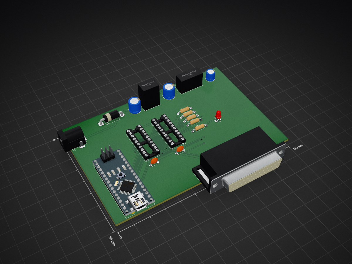
Emup adapter is an open-source printed circuit board by sharpdad, from the sharpdad/mod-emup-usb repository on GitHub, published under the MIT licence. It is a 2-layer board of 120 × 80 mm with 19 parts on 31 nets, routed with 383 tracks and 16 vias.
It is built around the 74HCT244D and 74HCT245. Its parts include 5 capacitors, 5 resistors, 4 ICs, 2 diodes and 2 connectors. It belongs with the interfaces and adapters boards of this library.


emup_adapter.py describes the board (parts, nets, placement);
./build.sh turns it into the KiCad schematic (emup_adapter.kicad_sch,
.pdf), a routed PCB (emup_adapter.kicad_pcb), DRC / ERC reports and fab
files (fab/: Gerber + drill zip, BOM). The KiCad files open and edit
normally in KiCad 8; if you edit the board by hand, don't re-run build.sh.
netclasses.json).Untested. Things to check on the first board: the box's current on each rail, the -12 V module's load, the DB25 pinout, and the strobe timing (the firmware uses ~1 us strobes, like the ISA bus).
| Qty | Value | Footprint | References |
|---|---|---|---|
| 4 | 10k | R_Axial_DIN0207_L6.3mm_D2.5mm_P10.16mm_Horizontal | R1, R2, R3, R4 |
| 2 | 100n | C_Disc_D5.0mm_W2.5mm_P5.00mm | C4, C5 |
| 1 | 100u 25V | CP_Radial_D8.0mm_P3.50mm | C1 |
| 1 | 12 V DC in (2.1 mm, centre +) | BarrelJack_Horizontal | J1 |
| 1 | 1N5822 (reverse protection) | D_DO-201AD_P15.24mm_Horizontal | D1 |
| 1 | 1k | R_Axial_DIN0207_L6.3mm_D2.5mm_P10.16mm_Horizontal | R5 |
| 1 | 220u 10V | CP_Radial_D8.0mm_P3.50mm | C2 |
| 1 | 47u 25V | CP_Radial_D6.3mm_P2.50mm | C3 |
| 1 | 74HCT244 | DIP-20_W7.62mm_Socket | U4 |
| 1 | 74HCT245 | DIP-20_W7.62mm_Socket | U3 |
| 1 | Arduino Nano (5 V) | Arduino_Nano | A1 |
| 1 | DB25 female (to the MOD-EMUP box) | DSUB-25_Female_Horizontal_P2.77x2.84mm_EdgePinOffset14.56mm_Housed_MountingHolesOffset15.98mm | J2 |
| 1 | LED (+5 V on) | LED_D3.0mm | D2 |
| 1 | RECOM R-78B5.0-2.0 | Converter_DCDC_RECOM_R-78B-2.0_THT | U1 |
| 1 | TRACO TMR 1-1211 (-12 V: +out to GND) | Converter_DCDC_TRACO_TMR-1-xxxx_Single_THT | U2 |
It measures 120 × 80 mm and has 2 copper layers, 1.6 mm thick.
19 parts, built around the 74HCT244D and 74HCT245. The full list of its parts is on this page, with links to each part's symbol and footprint where PCBKit's library has them.
From the sharpdad/mod-emup-usb repository on GitHub, at the commit this page was made from: the board is hardware/emup_adapter.kicad_pcb and its schematic hardware/emup_adapter.kicad_sch. PCBKit opens the board in the browser, with nothing to install.
Its repository publishes it under the MIT licence: you may reuse it on that licence's terms (keep the author's notice, and for a copyleft licence share your changes alike).


schlae/snark-barker-mca
A Sound Blaster compatible sound card for Micro Channel bus computers

artemisamsx/artemisa
Schematics, PCB designs and HDL simulations to build a 8-bits MSX computer


texelec/Resound-2-MCA-OPL3
Microchannel OPL3 Based Sound Card / Adlib Compatible
