4 layers100 × 68 mm

 SharKingStudios/RadRail-Badge
My personal badge created for the Fallout.
RadRail Badge is an open-source printed circuit board by SharKingStudios, from the SharKingStudios/RadRail-Badge repository on GitHub. It is a 2-layer board of 75 × 100 mm with 149 parts on 160 nets, routed with 1,671 tracks and 316 vias.
It is built around the ESP32-C3-WROOM-02-N4, AMS1117-3.3 and TX1812RWBA-F10, with the TS-1187A-B-A-B among its other parts. Its parts include 120 diodes, 8 capacitors, 8 switches, 5 resistors and 2 ICs. It belongs with the lEDs and displays boards and the ESP32 and RISC-V boards of this library.


A train-control PCB badge where RGB LEDs become trains moving through a virtual rail network.
RadRail is an interactive PCB badge inspired by hardware badge games and model railroads. The board lays out a miniature rail network using addressable RGB LEDs and train-track silkscreen artwork. The intended experience is to manually drive trains, switch routes, and watch movement around the board, with an autonomous/demo mode for when nobody is actively controlling it.
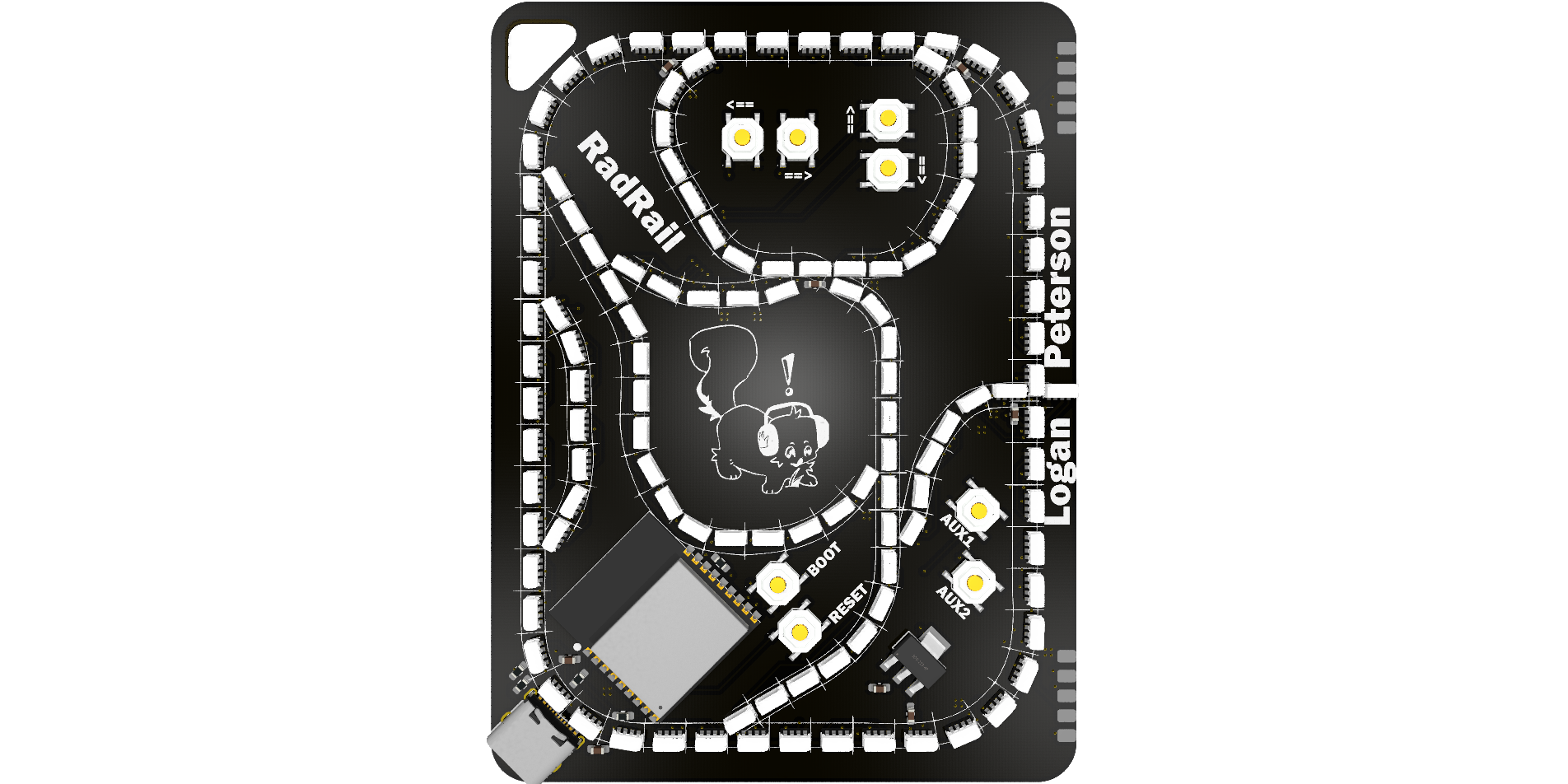
RadRail turns the PCB into both the controller and the display:
This is currently a hardware-first prototype. The KiCad design is present in this repo; firmware/gameplay logic is still in progress.
RadRail is inspired by interactive PCB badges and projects like Light Rail, a PCB train game where LEDs simulate trains moving along tracks and buttons change route states. RadRail takes that general idea and adds RGB LED animations to the tracks, along with the ability to link multiple boards together to create a larger network of tracks and trains.
The current PCB design includes:
The board is approximately 75 mm x 100 mm.
Planned gameplay ideas:
These are intended behaviors, not finished firmware features yet.
Firmware is in Firmware/ as a PlatformIO Arduino project for the ESP32-C3. It currently includes the PCB pin map, LED train rendering, directed route switching, basic train collision behavior, AUX train selection, and experimental board-link handoff over DETECT/TX/RX.
cd Firmware
pio run
pio run -t upload
pio device monitor
The train spawn table is near the top of Firmware/src/main.cpp.
The hardware is designed in KiCad. The PCB/production/ folder contains fabrication-related exports, including BOM, position, designator, and packaged production files.
Before ordering boards, verify:
Render and schematic images are included in Renders/:
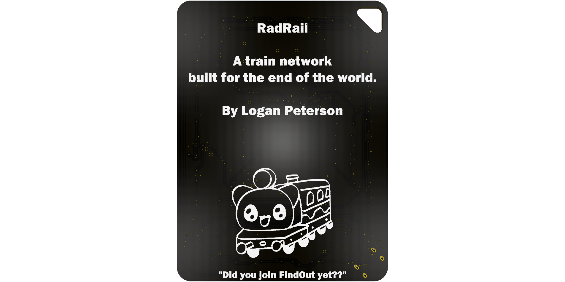
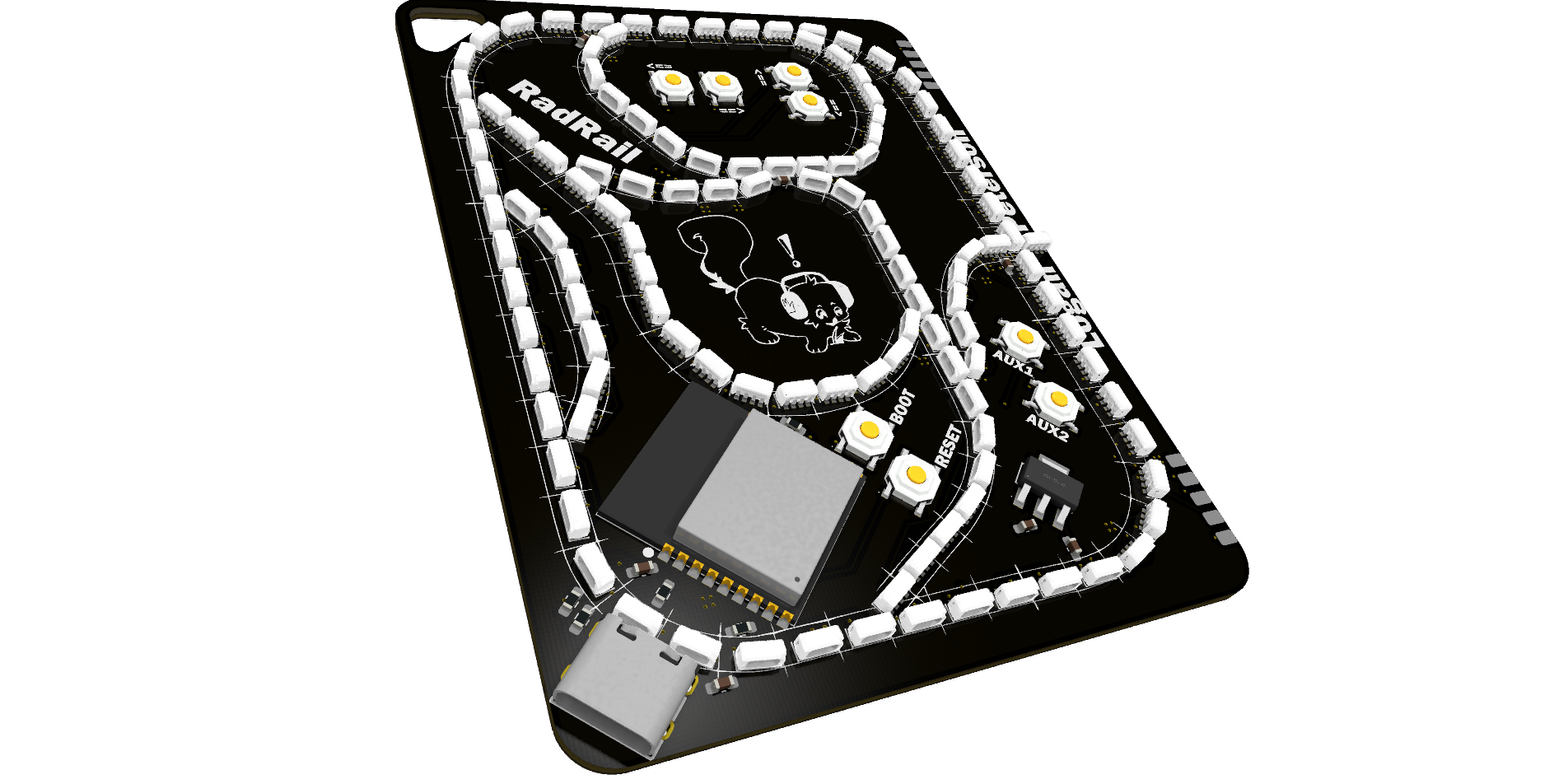
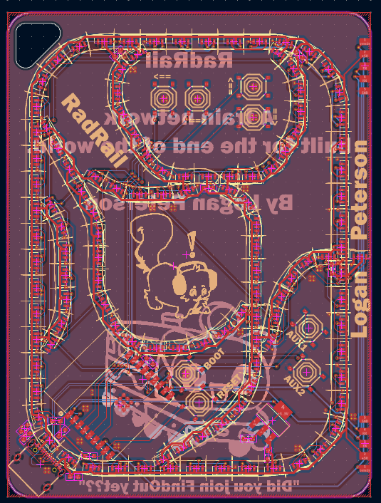
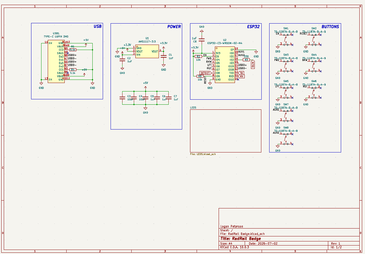
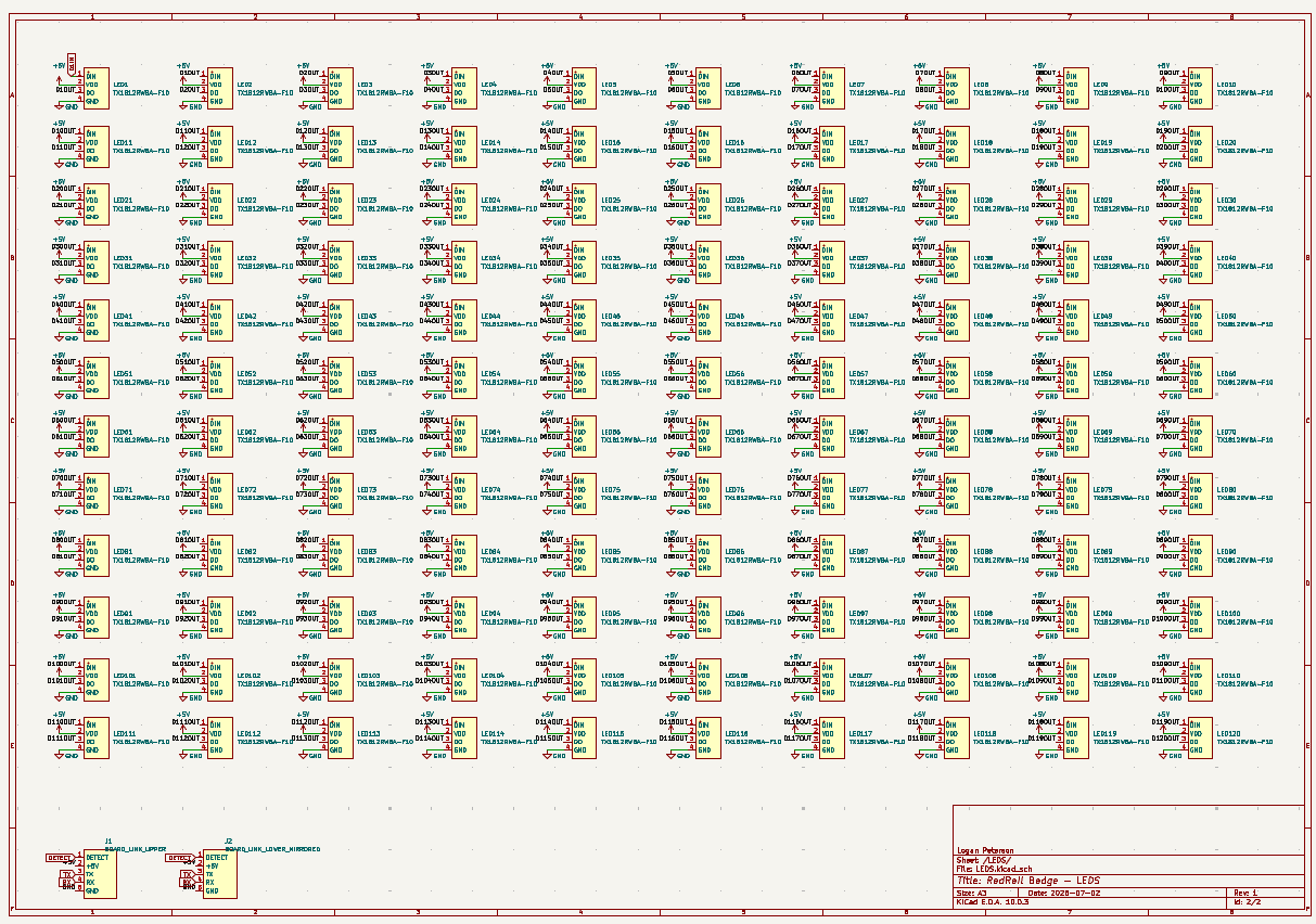
.
|-- PCB/
|   |-- RadRail Badge.kicad_pro
|   |-- RadRail Badge.kicad_sch
|   |-- LEDS.kicad_sch
|   |-- RadRail Badge.kicad_pcb
|   |-- libs/
|   `-- production/
|-- Firmware/
|   |-- platformio.ini
|   `-- src/
|-- Renders/
|-- README.mdPrototype hardware design is in progress. The board files and production exports are present, while firmware and final gameplay behavior still need to be written and tested.
| Qty | Value | Footprint | References |
|---|---|---|---|
| 120 | TX1812RWBA-F10 | imported_lcsc:LED-SMD_4P-L4.0-W1.7-R | LED1, LED10, LED11, LED100, LED101, LED102, LED103, LED104, LED105, LED106, LED107, LED108, LED109, LED110, LED111, LED112 +104 |
| 8 | TS-1187A-B-A-B | imported_lcsc:SW-SMD_4P-L5.1-W5.1-P3.70-LS6.5-TL_H1.5 | SW1, SW2, SW3, SW4, SW5, SW6, SW7, SW8 |
| 6 | 1uF | Capacitor_SMD:C_0603_1608Metric_Pad1.08x0.95mm_HandSolder | C1, C2, C5, C6, C7, C8 |
| 3 | LOGO | LOGO | G***, G***, G*** |
| 2 | 10k | Resistor_SMD:R_0603_1608Metric_Pad0.98x0.95mm_HandSolder | R2, R5 |
| 2 | 5.1k | Resistor_SMD:R_0603_1608Metric_Pad0.98x0.95mm_HandSolder | R1, R4 |
| 1 | 10uF | Capacitor_SMD:C_0603_1608Metric_Pad1.08x0.95mm_HandSolder | C4 |
| 1 | 10uf | Capacitor_SMD:C_0603_1608Metric_Pad1.08x0.95mm_HandSolder | C3 |
| 1 | 330 | Resistor_SMD:R_0603_1608Metric_Pad0.98x0.95mm_HandSolder | R3 |
| 1 | AMS1117-3.3 | imported_lcsc:SOT-223-3_L6.5-W3.4-P2.30-LS7.0-BR | U1 |
| 1 | BOARD_LINK_LOWER_MIRRORED | imported_lcsc:SMD_BOARD_LINK_5P_MIRRORED | J2 |
| 1 | BOARD_LINK_UPPER | imported_lcsc:SMD_BOARD_LINK_5P | J1 |
| 1 | ESP32-C3-WROOM-02-N4 | imported_lcsc:BULETM-SMD_ESPRESSIF_ESP32-C3-WROOM-02-N4-4MB | U2 |
| 1 | TYPE-C 16PIN 2MD | imported_lcsc:USB-C-SMD_TYPE-C-16PIN-2MD-073 | USB1 |

develmusa/Thermomine
Thermomine is a 3D-printed naval mine that sits on the gravel of your tank. A sealed LED inside glows blue when the water is too cold, green when it's just right, and red when it's too warm.

RSXLX/sunny-the-growing-sunflower-lamp
SUNNY — The Growing Sunflower Lamp | A personal lamp with customizable exteriors, traceable fabrication, and a local creative workspace.

nushackers/hnr26-badge-quacknroll
Hack&Roll 2026 "Quack & Roll" badge source files, for both hardware and firmware

dominicmason555/lightweatherv3
Open-Source Hardware and Firmware IO and Temperature/Pressure/Humidity/Gas Sensor MQTT Board


verIdyia/astra-board
ESP32-C3 development board: a documented AI-assisted PCB experiment

It measures 75 × 100 mm and has 2 copper layers, 1.6 mm thick.
149 parts, built around the ESP32-C3-WROOM-02-N4, AMS1117-3.3, TX1812RWBA-F10 and TS-1187A-B-A-B. The full list of its parts is on this page, with links to each part's symbol and footprint where PCBKit's library has them.
From the SharKingStudios/RadRail-Badge repository on GitHub, at the commit this page was made from: the board is PCB/RadRail Badge.kicad_pcb and its schematic PCB/LEDS.kicad_sch. PCBKit opens the board in the browser, with nothing to install.
Its repository states no licence, so its author keeps all rights: ask SharKingStudios before reusing the design.