


4 layers40 × 80 mm

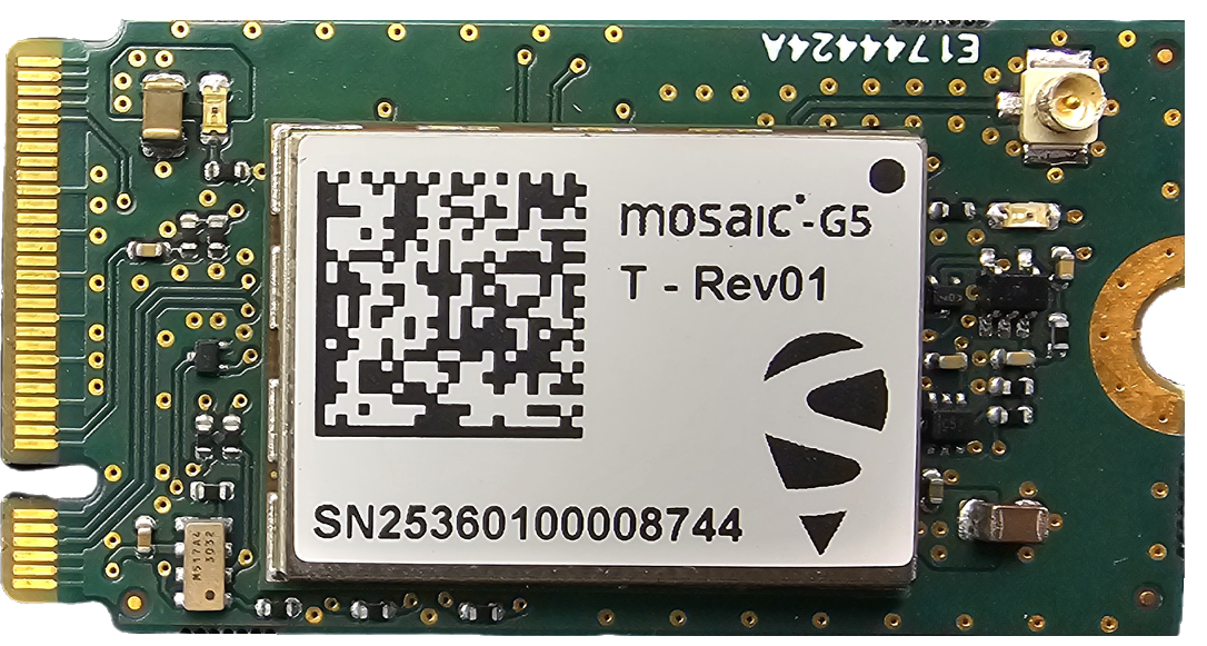
moTi: Is an M.2 Key B open source HW for mosaic G5-T GNSS modules of Septentrio
MoTi is an open-source printed circuit board by septentrio-gnss, from the septentrio-gnss/moTi repository on GitHub. It is a 4-layer board of 22 × 42 mm with 30 parts on 87 nets, routed with 268 tracks and 176 vias.
It is built around the SN74LVC1G3157DRLR-TP and U.FL-R-SMT-1(01). Its parts include 8 resistors, 6 capacitors, 3 ICs, 2 diodes and 2 transistors.
| Role | Contact |
|---|---|
| Author | laekaz |
| Maintainer | Septentrio GNSS GitHub User |
| License | OCP CLA |
| Project | Stargate |

This project is co-funded by the European Union Agency for the Space Programme under the Fundamental Elements Grant EUSPA/GRANT/02/2024

moTi is a timing module that provides accurate and reliable synchronisation signals for time-sensitive systems. It is based on a standardised M.2 form factor that can be easily integrated into compatible carrier boards such as the Open Compute Project (OCP) Time Card. This board receives precise timing information from Septentrio’s mosaic-G5 T GNSS (Global Navigation Satellite System) module. It then generates synchronisation outputs such as Pulse Per Second (PPS) and Time of Day (ToD) data. These signals are then used to synchronise services, in network interface cards (NICs), and other hardware in data centres and communication systems.
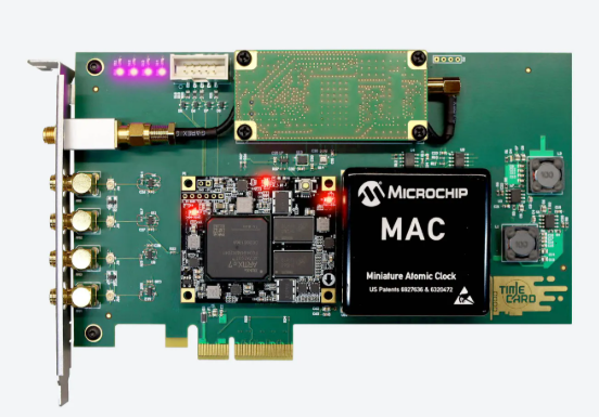
A Time Card is a PCIe card that is designed to plug into a server and provides precision time outputs such as PPS (Pulse Per Second) and ToD (Time of Day). It provides this precise timing to the server’s clock and network hardware, enabling high-accuracy synchronisation using protocols like the NTP or PTP. moTi connects to the Time Card as a timing source, supplying the card with GNSS time signals in standardised form factor.
Originally, it was developed by Meta and released through the Open Compute Project
More information about the Time Card on this link or Github
Septentrio mosaic-G5 T is a compact, low-power GNSS timing receiver module with multi-band, multi-frequency capability. Designed for critical infrastructure and other applications where resilient and precise timing is essential, it ensures maximum security and uptime. It tracks all Global Navigation Satellite System (GNSS) constellations and supports both current and future signals.

Septentrio is a leading company that designs, manufactures and sells high precision and multi-frequency GPS/GNSS receivers for demanding applications. Septentrio products are used in different industries including automotive, marine, construction, rail, machine control, logistics, precision agriculture, geographic information systems (GIS), Unmanned Aerial Vehicles (UAVs), surveying, mapping and scientific development. Septentrio’s receivers constantly deliver accurate and precise GNSS positioning scalable to centimetre-level and designed to perform perfectly in challenging environments.
Septentrio's technology offers high accuracy and reliability thanks to GNSS + algorithms as well as Advanced interference Monitoring and Mitigation (AIM+) This protects your application against jamming (RF interference) and spoofing (malicious attacks).
For more information about Septentrio products go to https://www.septentrio.com/.
This board is open source to encourage collaboration, customization, and innovation. By making the design files publicly available, developers and engineers can study, modify, and adapt the hardware to fit their specific applications, reducing development time and cost. It also promotes transparency and avoids vendor lock-in, allowing users to fully understand and control the design.
This project is offered as-is. The main interfaces have been tested, but the design has not been fully checked or approved by the author or Septentrio. You are responsible for how you use it in your own projects. For guidance on working with Septentrio’s GNSS mosaic modules, we suggest reaching out to Septentrio directly.
Support website: https://www.septentrio.com/en/support
This open-source project contains the following files for designers, producers and integrators around Septentrio's mosaic modules.
| Files | description |
|---|---|
| moTi.kicad_pro | KiCAD project |
| moTi.kicad_sch | KiCAD schematic |
| mosaic-G5.kicad_sch | KiCAD mosaic-G5 schematic sheet |
| M2_Edge connector.kicad_sch | KiCAD M.2 Key B schematic sheet |
| Clockdetect.kicad_sch | KiCAD clock schematic sheet |
| moTi.kicad_pcb | KiCAD PCB layout |
| moTi_Schematics.pdf | schematic PDF |
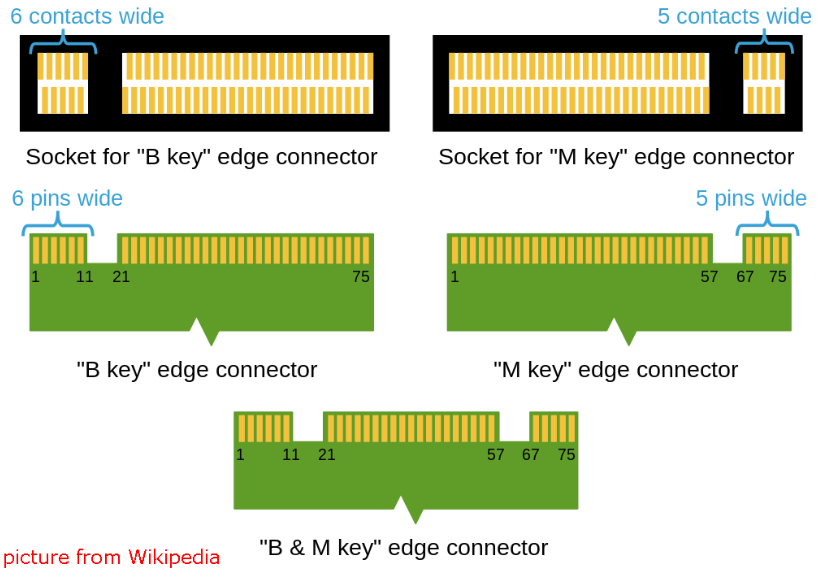
The M.2 form factor provides a compact interface for expansion cards.The moTi board is M.2 Key B connector, but it can also fit into some Key M or B+M slots. B+M slots are designed with extra notches so they accept both Key B and Key M modules, allowing flexibility in installation. This means your Key B board can interconnect with a Key M-compatible slot as long as it’s a B+M slot, ensuring proper electrical connections and compatibility.
Before you physically install anything:
Boot Linux with the Time Card inserted.
If your Linux system uses the Kernel 5.15 or newer the Time Card driver is already included. So the kernel loads the driver automatically.
The devices are exposed by the driver like:
/dev/ptpX -> PHC device
/dev/ppsY -> PPS pulse signal
/sys/class/timecard/ocp0/-> status and attributes
These are the time interface paths in the OS.
Command example to see the devices:
ls -l /sys/class/timecard/ocp0/This will show many devices including GNSS, PPS, PHC clock and atomic clock serial
Once Linux has detected the Time Card:
/dev/ttyS7 or similar.gpsd or a tool like cgps to check the satellite status.For example:
gpsd /dev/ttyS5tio -b 115200 /dev/ttyS5tio -b 115200 /dev/ttyS0available_sma_outputs contains all available outputs
To list available outputs:
cat available_sma_outputs
10MHz PHC MAC GNSS1 GNSS2 IRIG DCF GEN1 GEN2 GEN3 GEN4 GND VCC cat /sys/class/timecard/ocp0/available_sma_outputs Output on SMA:
echo OUT: PHC >> sma1echo OUT: MAC >> sma1echo OUT: GNSS1 >> sma1The PHC (Precision Hardware Clock) device exposed by the driver can be used to sync the Linux system clock
Once everything is configured:
This means your server can act as a time source for the whole infrastructure.
These are normal steps to get the Time Card recognized by Linux.
For orders of the mosaic-G5 T, please contact Septentrio
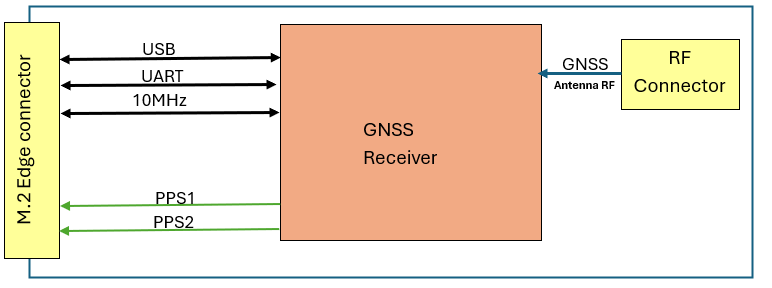
The above block diagram is showing the overview communication between the antenna, receiver and M.2 edge connector.
| interface signals | I/O Type | Voltage | Signal Description |
|---|---|---|---|
| Power | Power | 3.3V | 3.3 V Supply pin. |
| UART | I&O | 3.3V | Universal Asynchronous Receiver Transmitter, RX & TX |
| USB | I/O | 3.3V | Universal Serial Bus interface, USB D+ and D− differential data lines |
| PPS Out 1 | O | 3.3V | Pulse Per Second signal out#1. |
| PPS Out 2 | O | 3.3V | Pulse Per Second signal out#2. |
| Event 1 (PPS IN) | I | 3.3V | Pulse Per Second reference signal input. If not used, connect to ground on Platforms. |
| CLK_IN | I | 3.3V | 10MHz reference clock input. If not used, connect to ground |
| CLK_OUT | O | 3.3V | 10MHz output clock. |
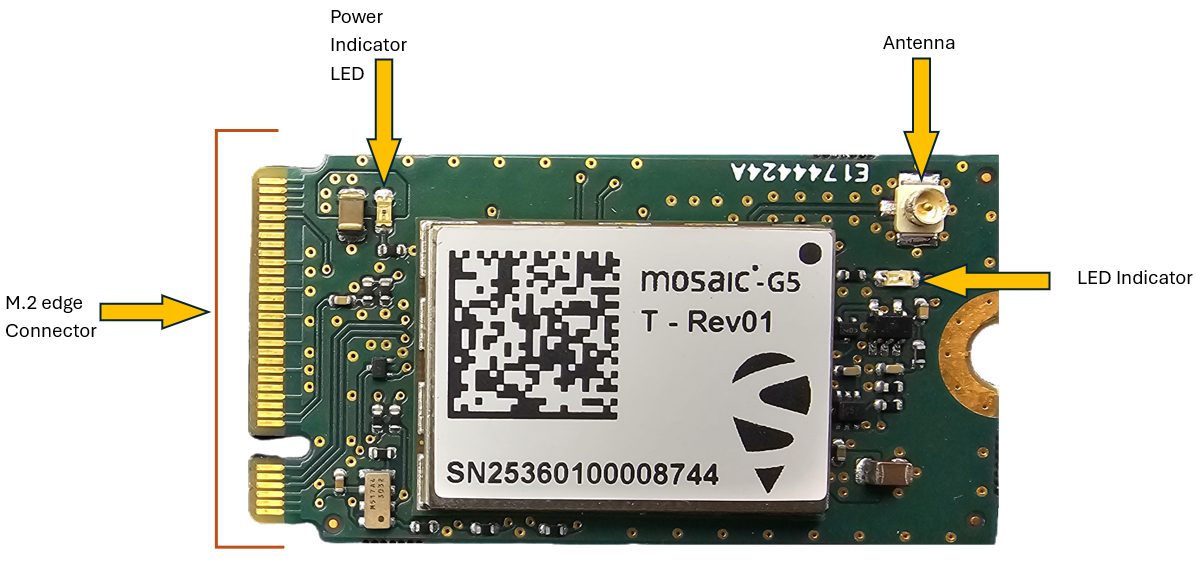
| LED D1 | O | 3.3V | Power Supply indicator |
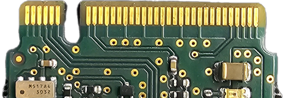
| Pin # | Signal |
|---|---|
| 7 | USB D+ |
| 9 | USB D- |
| 23 | 10MHz clock input |
| 67 | nRST_IN |
| 2, 4 | VBAT |
| 10 | LED#1 |
| 20 | PPS2 output |
| 22 | Ref_CLK_SEL |
| 24 | PPS input |
| 46 | PPS1 output |
| 48 | 10MHz clock output |
| 62 | UART COM1 Rx |
| 64 | UART COM1 Tx |
| 70, 72, 74 | Power 3.3V |
| GND | GND |
USB 2.0 pins USB_D+ and USB_D- When the module is inserted into a card that supports USB pins on its edge connector, the USB interface works just like it would on any other device. It is used for data, configuration, and control. It carries data such as , Time of Day (ToD) for the GNSS, diagnostic messages and firmware update channels. The Time Card will act as the USB host.
UART (Universal Asynchronous Receiver Transmitter) This is a standard serial port using TX and RX pins.
PPS Out timing reference signal output. This supplies high-precision timing references directly into the Time Card clocking system.
Event 1 (PPS IN) This pin detects a pulse from an external device and records the exact GNSS time when the pulse happened. It is connected to the eventB pin of the mosaic-G5 T
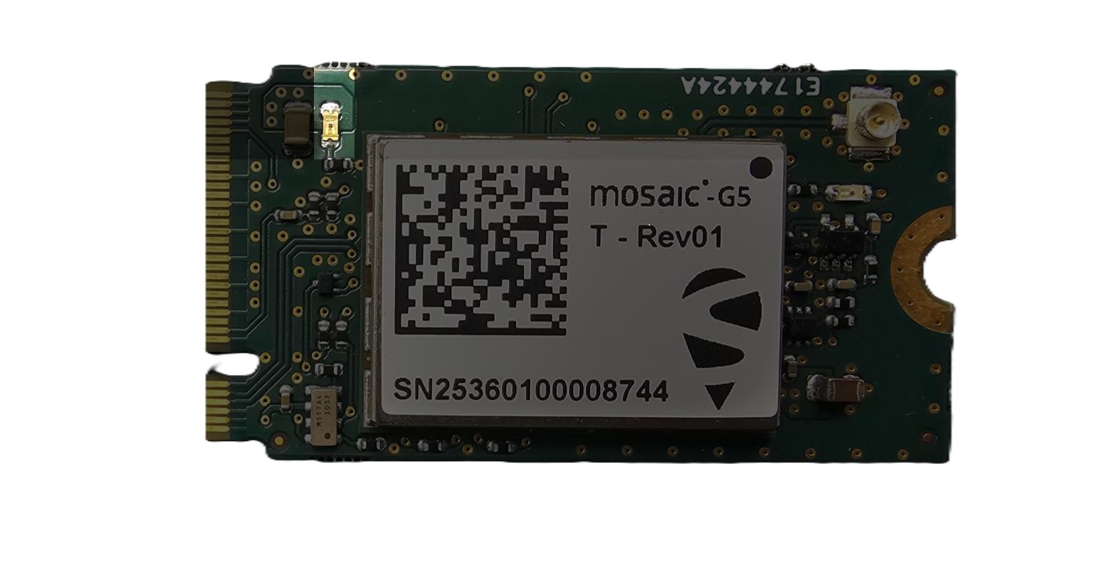 This LED indicates whether the Module is ON/OFF
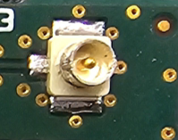
The board provides a U.FL (UMCC) 50 Ω PCB receptacle for connecting an external GNSS antenna. This miniature RF connector is commonly used in compact embedded and wireless systems due to its small size and reliable high-frequency performance.
Connector Details
Notes
| Qty | Value | Footprint | References |
|---|---|---|---|
| 6 | Fiducial | Fiducial:Fiducial_0.5mm_Mask1mm | FID1, FID2, FID3, FID4, FID5, FID6 |
| 4 | 10k | Resistor_SMD:R_0402_1005Metric | R9, R10, R11, R14 |
| 3 | 1.0k | Resistor_SMD:R_0402_1005Metric | R1, R3, R4 |
| 3 | 1.0n | Capacitor_SMD:C_0402_1005Metric | C6, C8, C9 |
| 2 | LED | LED_SMD:LED_0603_1608Metric | D1, D2 |
| 1 | 1.5k | Resistor_SMD:R_0402_1005Metric | R2 |
| 1 | 100n | Capacitor_SMD:C_0402_1005Metric | C2 |
| 1 | 22u | Capacitor_SMD:C_0805_2012Metric | C1 |
| 1 | 47u | Capacitor_SMD:C_0805_2012Metric | C3 |
| 1 | NTK3043NT1G | NTK3043NT1G:MMBT2907AM3T5G | Q2 |
| 1 | NTK3139PT5G | NTK3139PT5G:SOTFL40P120X55-3N | Q1 |
| 1 | SN74LVC1G3157DRLR | SN74LVC1G3157DRLR:SOTFL50P160X60-6N | U5 |
| 1 | TLV3511DCKR | TLV3511DCKR:SOT65P210X110-5N | U2 |
| 1 | U.FL-R-SMT_10_ | U.FL-R-SMT(10):UFLRSMT10 | J1 |
| 1 | mosaic-G5 T | mosaic-G5-T:LGA54_MOSAIC-MINI_SEP | U1 |
| 1 | ~ | M.2 Edge connector:NGFF_B | J2 |
| 1 | ~ | PCB_label:PCB_label | PCB1 |

RedBulletTooling/crypsis-public
This contains, all files from hardware to software production and all to make Crypsis


Boardoza/Boardoza_RFM6601W_LoRa_Wireless_Breakout_Board
LoRa wireless communication module with built-in Cortex-M4 MCU, multi-band support, and UART interface.

justinfederico/STM32testPCB
Custom STM32WB microcontroller to practice my PCB schematic and layout skills. Looking to get it printed soon! Bear in mind that this is an ameuter project, so there will probably be errors aplenty.
It measures 22 × 42 mm and has 4 copper layers, 0.91 mm thick.
30 parts, built around the SN74LVC1G3157DRLR-TP and U.FL-R-SMT-1(01). The full list of its parts is on this page, with links to each part's symbol and footprint where PCBKit's library has them.
From the septentrio-gnss/moTi repository on GitHub, at the commit this page was made from: the board is KiCad_Files/KiCad/moTi/moTi.kicad_pcb and its schematic KiCad_Files/KiCad/Library/M.2-Card-Footprints-main/M.2-Card-Footprints-main/KiCad/M.2-Templates.kicad_sch. PCBKit opens the board in the browser, with nothing to install.
Its repository states no licence, so its author keeps all rights: ask septentrio-gnss before reusing the design.