2 layers18.5 × 11.1 mm
Switch
byrantech/laptop
anyon_e, a highly integrated, high end, open source laptop. Attempt the impossible.
6 parts4.3kMIT
 sensai7/VolcaModularMidi66
Mod to add MIDI IN to a Korg Volca Modular
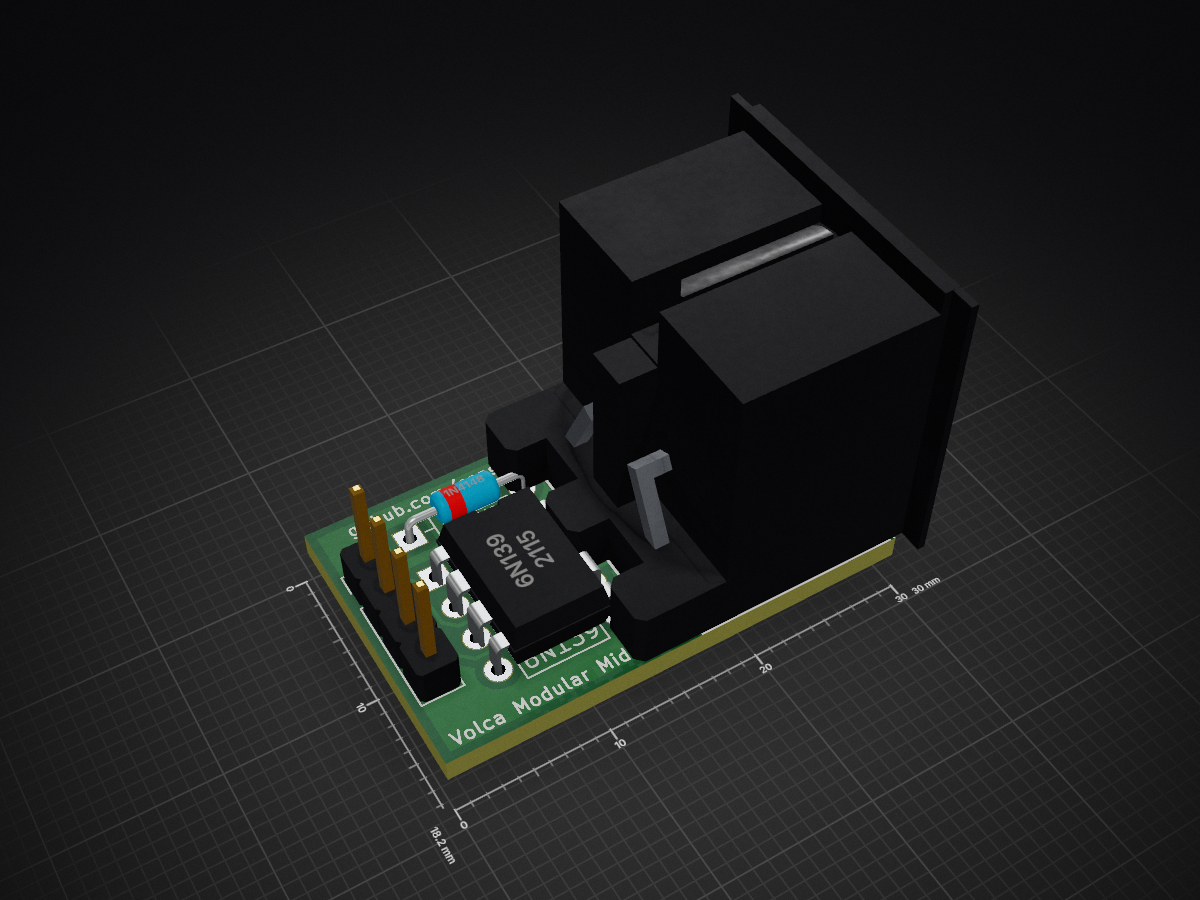
VolcaModularMidi is an open-source printed circuit board by sensai7, from the sensai7/VolcaModularMidi repository on GitHub. It is a 2-layer board of 30 × 18.2 mm with 6 parts on 13 nets, routed with 42 tracks and 2 vias.
Its parts include 2 resistors, 2 connectors, 1 IC and 1 diode.
This is a hardware mod to add MIDI IN capability to the Korg Volca Modular


BEFORE YOU BEGIN:
This installation process requires you to open your Korg volca Modular, most likely voiding the warranty. The creator of this mod and all the contributors of this project are not to be held responsible for possible malfunctions caused by this process.
In these example photos the mod was already installed (the red/orange/yellow/green cables), but I repeated the process to take the photos and make it easier to explain.
Read the tutorial and make sure you understand all the steps before proceeding.
Be sure to have the following tools:
1- Unscrew the screws from the back.

2- Gently pull from a potentiometer to detach the blue case from the circuit.

3- Unplug the batteries connector (red/black cables) in the top right of the board

4- Lay the circuit down, be careful with the speaker connection (orange/brown cables)

5- You can see the holes now, they're labelled as MIDI_RX, MIDI_TX, +3.3V, GND

6- Unpeel the black tape and unplug the keyboard connector (white/orange cables)


7- Unscrew the 6 screws attaching the main board with the keyboard board.

8- Sit the main board on it's place in the blue case and open a hole on the right side enough to let the four cables go through. Then solder the four cables facing down and snip the excess wire. (disregard the quality of mine, I don't have the tools nor skill for these things :( )

9- Repeat the process from steps 7 to 1 in inverse order to reassemble the unit.
If you have the tools, and patience, you can glue the female connections to the case so you can plug it directly (here's a poorly photoshopped concept illustrating it)

If you prefer to use a 3.5mm stereo jack instead of the big DIN-5 connector, here's another poorly photoshopped concept

| Qty | Value | Footprint | References |
|---|---|---|---|
| 1 | 1N4148 | Diode_THT:D_DO-35_SOD27_P7.62mm_Horizontal | D1 |
| 1 | 220 | Resistor_THT:R_Axial_DIN0207_L6.3mm_D2.5mm_P7.62mm_Horizontal | R1 |
| 1 | 270 | Resistor_THT:R_Axial_DIN0207_L6.3mm_D2.5mm_P7.62mm_Horizontal | R2 |
| 1 | 6N139 | Package_DIP:DIP-8_W7.62mm | U1 |
| 1 | Conn_01x04_Male | Connector_PinHeader_2.54mm:PinHeader_1x04_P2.54mm_Vertical | J1 |
| 1 | MIDI_IN | SensaiLib:din-5 | J2 |
byrantech/laptop
anyon_e, a highly integrated, high end, open source laptop. Attempt the impossible.


Jcparkyn/dpoint
Open-source digital stylus using camera tracking and inertial measurements

VoronDesign/Voron-Hardware
Cool Hardware designed by the Voron Design group

hoglet67/RGBtoHDMI
Bare-metal Raspberry Pi project that provides pixel-perfect sampling of Retro Computer RGB/YUV video and conversion to HDMI

hackclub/OnBoard
💡 Join 1,000 teenagers and make your first PCB with a $100 grant!

Luos-io/luos_engine
Open-source and real-time orchestrator for cyber-physical-systems, to easily design, test and deploy embedded applications and digital twins.

It measures 30 × 18.2 mm and has 2 copper layers, 1.6 mm thick.
6 parts. The full list of its parts is on this page, with links to each part's symbol and footprint where PCBKit's library has them.
From the sensai7/VolcaModularMidi repository on GitHub, at the commit this page was made from: the board is VolcaModularMidi.kicad_pcb. PCBKit opens the board in the browser, with nothing to install.
Its repository states no licence, so its author keeps all rights: ask sensai7 before reusing the design.