2 layers77.2 × 69.8 mm

 semi-simple/backporch6
Classic gaming consoles to SCART/PVM/OSSC/RetroTINK adapter
Backporch is an open-source printed circuit board by semi-simple, from the semi-simple/backporch repository on GitHub, published under the Apache-2.0 licence. It is a 2-layer board of 53.3 × 32.4 mm with 31 parts on 35 nets, routed with 224 tracks and 5 vias.
It is built around the EL1883ISZ, 35RAPC4BH3 and MD-80SM, with the MD-90SM among its other parts. Its parts include 11 capacitors, 9 resistors, 4 connectors and 1 IC.


Backporch is a board to connect many classic gaming consoles with widely available and easily made cables with no components inside. Backporch can then be connected to PVMs (via HD15), Extron matrices, SCART TVs or OSSC / RetroTINK devices.
PVMs and Extron matrices can be connected with a simple VGA to BNC or VGA to VGA cable. SCART TVs can be connected with a component-free Mini-DIN 8 to SCART cable.
It is also possible to use Backporch to adapt any SCART cable into a TTL sync output suitable for PVMs.
Backporch includes the necessary resistors, coupling caps and a sync stripper / sync booster (Renesas EL1883 or Renesas ISL59885) for an excellent sync signal. Schematics here.
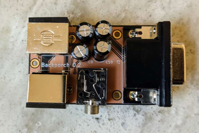
There are two inputs:
The (mini) DIN 9 connector is suitable for consoles that output directly from a video amplifier to the back of the console. Cables for such consoles typically have impedence matching resistors as well as coupling capacitors.
The (mini) DIN 8 connector (also usable as output) can be used to turn any existing SCART setup into a TTL sync setup suitable for PVMs. All one needs is a simple passive SCART to (mini) DIN 8 cable such as the ones compatible with the Framemeister XRGB mini.
It also can be used directly as input with a staight DIN 8 cable for consoles that have retro mods, such as the NES RGB mod or some superguns.
There are two video outputs:
The DE-15/HD-15 ("VGA") connector is suitable for PVMs (or the DE-15 input on the OSSC) and is best used with widely available HD15 to BNC cables. It will output composite sync or separate H-SYNC and V-SYNC depending on the JP3 jumper.
The (mini) DIN 8 connector (also usable as input) is suitable for SCART output using a widely available mini DIN 8 to SCART cable. This output can also be used to connect directly to a Framemeister XRGB mini with a simple mini DIN 8 cable.
Jumpers:
Sega 32X cables work well, but all pins need to be connected. Some high quality, proper 32X cables don't have PIN 2 (5V) connected. Most "cheap" cables on Ebay have all pins connected. Some bad cables don't have ground connected.
(You can use cables without PIN 2 if you don't solder U1 and change JP1)
If your Super Nintendo is modded with an RGB bypass mod, you can build a simple cable from MultiAV to mini-din 8. Wire sync (Pin 3) from either composite or Luma (better!). This will work for either PAL or NTSC consoles! If you have CSYNC wired, you can use that instead, but ideally configure your RGB bypass board to output 75 Ohm CSYNC.
Unmodded Super Nintendo are not supported at this time as they require coupling capacitors (things will work without them, but this setup might draw excessive current from the video amplifiers).
Of course, if you already have a SCART cable for your Super Nintendo, you can still use Backporch to restore TTL sync and plug it to a PVM.
Either with Terraonion's SSDS3, Insurrection Industries' Spark Plug or the db GrafxBooster TTP:
If you already have a SCART cable for your device and all you need is a sync stripper / booster to connect to a PVM or an Extron matrix, you can use any SCART to mini DIN 8 cable, such as the ones used for the Framemeister XRGB mini.
Ideally, proper analog video transmission should happens over 75 Ohm coaxial cables. Proper impedence matching requires a 75 Ohm resistor at the source and a 75 Ohm resistor at the destination. This is why many retro-gaming cables that have resistors meant for the source inside the SCART (near the destination) are not proper. At the frequencies used in classic gaming console signals, this only really matters for very long cables though.
You should strive to use high quality shielded cables to Backporch and keep them short. If only one of those properties holds true, you should still be fine. Properly shielded 75 Ohm cables used from Backporch's outputs can be long.
Use this issue for a discussion of where to source good cables.
You can order the board directly from Oshpark here or download the Gerber files from them and send those to your favorite manufacturer.
You can order the needed components by using this BOM file. If you order from Digi-Key, you can simply upload this file to them.
It's a small deck at the back of your console (back porch). It's also a reference to the blanking interval after the sync pulse in video signals.
Maybe not. For many inputs, if you know what you're doing, you can remove all components related to sync stripping and use JP1 to send sync directly to HSYNC on the DE-15 port. For THS737X mods ("RGB bypass"), coupling capacitors are not needed. Remove the big electrolytic capacitors and bridge the footprint of the small ones.
The DE-15 input (AV3) on the OSSC does not have a proper low-pass filter. You can use the SCART input instead, or you can route the RGB lines to AV2 instead (via BNC/RCA adaptors and VGA/BNC breakout cables) and use the "AV3 use alt. RGB" option on the OSSC.
You're in luck: it works as a drop-in replacement for U1. Just keep R2 unpopulated and replace C2 with a 56nF X7R grade capacitor.
| Qty | Value | Footprint | References |
|---|---|---|---|
| 7 | 0.1uF | Capacitor_SMD:C_1206_3216Metric_Pad1.42x1.75mm_HandSolder | C1, C2, C3, C5, C7, C9, C11 |
| 7 | 75R | Resistor_SMD:R_1206_3216Metric_Pad1.42x1.75mm_HandSolder | R1, R3, R4, R5, R6, R8, R9 |
| 4 | 330uF | Capacitor_THT:CP_Radial_D6.3mm_P2.50mm | C4, C6, C8, C10 |
| 3 | MountingHole | MountingHole:MountingHole_2.2mm_M2_ISO7380_Pad | H1, H2, H3 |
| 1 | 35RAPC4BH3 | project-footprints:SWITCHCRAFT_35RAPC4BH3 | J4 |
| 1 | 470R | Resistor_SMD:R_1206_3216Metric_Pad1.42x1.75mm_HandSolder | R7 |
| 1 | 681kR | Resistor_SMD:R_1206_3216Metric_Pad1.42x1.75mm_HandSolder | R2 |
| 1 | CSYNC/HSYNC | Jumper:SolderJumper-3_P1.3mm_Open_Pad1.0x1.5mm | JP3 |
| 1 | DB15_Female_HighDensity_MountingHoles | project-footprints:VGA_CONN | J3 |
| 1 | EL 1883 bypass | Jumper:SolderJumper-3_P1.3mm_Open_Pad1.0x1.5mm | JP1 |
| 1 | EL1883ISZ | project-footprints:SOIC127P600X175-8N | U1 |
| 1 | MD-80SM | project-footprints:CUI_MD-80SM | J2 |
| 1 | MD-90SM | project-footprints:CUI_MD-90SM | J1 |
| 1 | SolderJumper_2_Bridged | Jumper:SolderJumper-2_P1.3mm_Open_Pad1.0x1.5mm | JP2 |
It measures 53.3 × 32.4 mm and has 2 copper layers, 1.6 mm thick.
31 parts, built around the EL1883ISZ, 35RAPC4BH3, MD-80SM and MD-90SM. The full list of its parts is on this page, with links to each part's symbol and footprint where PCBKit's library has them.
From the semi-simple/backporch repository on GitHub, at the commit this page was made from: the board is backporch.kicad_pcb. PCBKit opens the board in the browser, with nothing to install.
Its repository publishes it under the Apache-2.0 licence: you may reuse it on that licence's terms (keep the author's notice, and for a copyleft licence share your changes alike).


db-electronics/triple-bypass-kicad
An audio and video bypass circuit for the Sega Genesis

starlightk7/OpenFC
OpenFC Repository for Reproduction PCBs for Early 1980's Famicom Boards. Placeholder: Release Coming Soon!

db-electronics/MD-90SM-breakout-kicad
A simple breakout board for the MD-90SM Mini-Din 9 (Sega Genesis 2 A/V) connector

MEGA65/mega65-r3-expansion-board
Expansion board for the MEGA65 R3+ Main Boards

ynsta/fwrtss
Open source hardware and software project of a regulated soldering station for RT soldering tips
