4 layers165 × 160 mm

 sebmorales/ENHP9
Experiments in Networked Hardware Performance
ENHP eleklekha is an open-source printed circuit board by sebmorales, from the sebmorales/ENHP repository on GitHub. It is a 2-layer board of 76.3 × 105.1 mm with 49 parts on 80 nets, routed with 685 tracks and 63 vias.
It is built around the ESP32-DEVKITC-VE, LSM303C and MIC5225-3.3YM5, with the BC817, 1N4148W and KF142V-5.08-3P among its other parts. Its parts include 15 resistors, 8 connectors, 7 capacitors, 4 ICs and 3 diodes. It belongs with the ESP32 boards of this library.


Woo! You got your board on the mail, or maybe we gave it to you in person, now, what is it? What is it for?
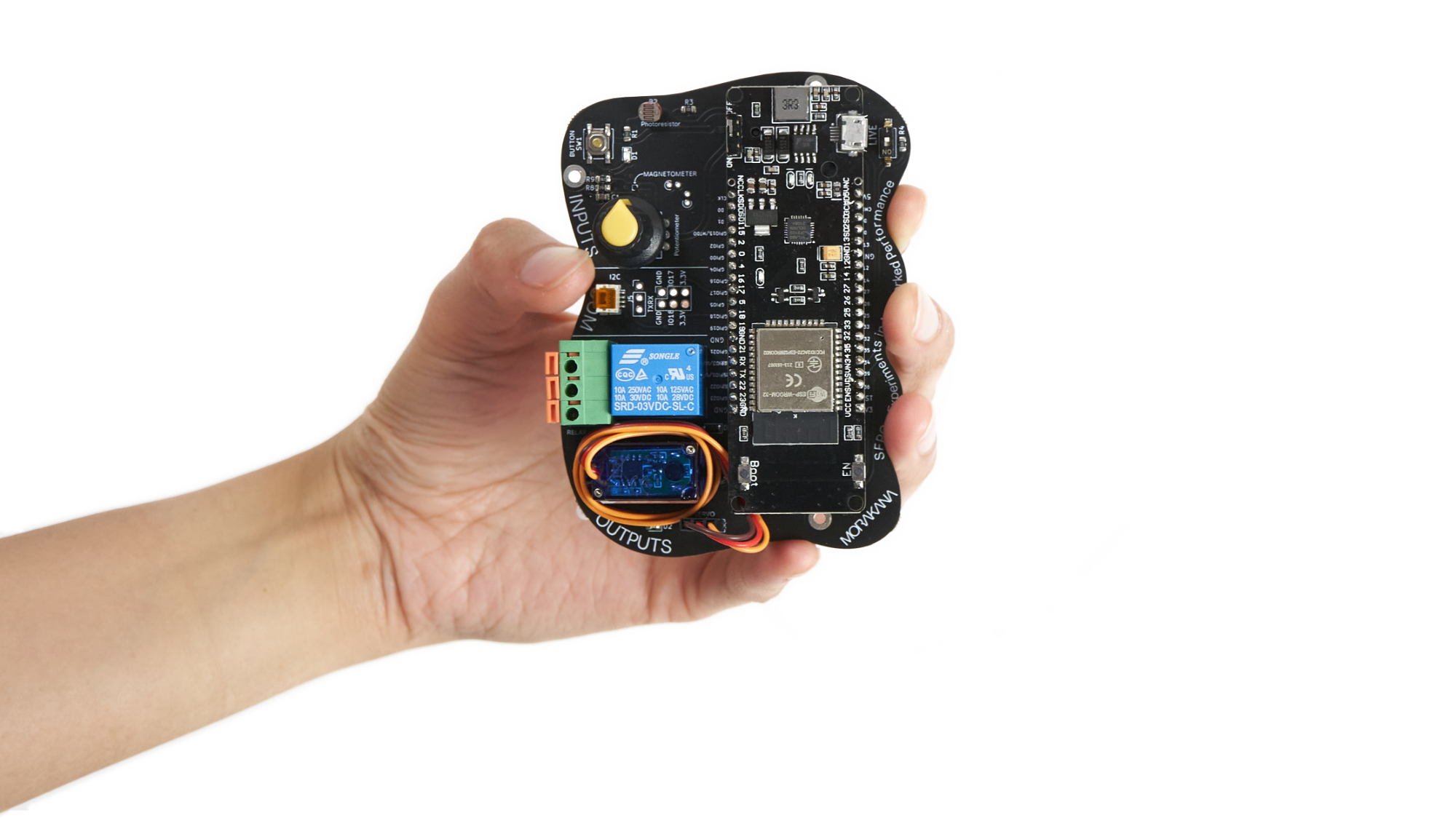
This board is based on a ESP32 microcontroller, but it also has some other components to help us get started connecting the digital world and our tangible one. We will go more in depth during class, but for now, here is a quick manual to get you going.
By default, the board is already pre-programmed, so you don’t have to worry about that. But if you want to make changes, you are more than welcome to do so. We will soon update this same doc to share the code and schematics.
Note: The board in a bit of an experimental stage and we are still trying to figure things out, so please share any feedback and bugs as you find them :)
Each board has a unique name (written by hand on the back of the board). Let’s get the boards connected and start sharing light data!
If you go to the webpage https://hardwaremovement.com you will see a grid of boxes, each with a name. At the time I took this image, there were only three boards on there, hopefully by now there are many more. As new boards connect, the grid starts getting updated with each boards' last photoresistor reading.

This website is only collecting light information, and since other people will likely connect at different times, feel free to come back and see how the collaborative page is changing over time. Feel free to place the board anywhere indoors and see how that impacts the page.
Turn on the switch on the ESP32 board.
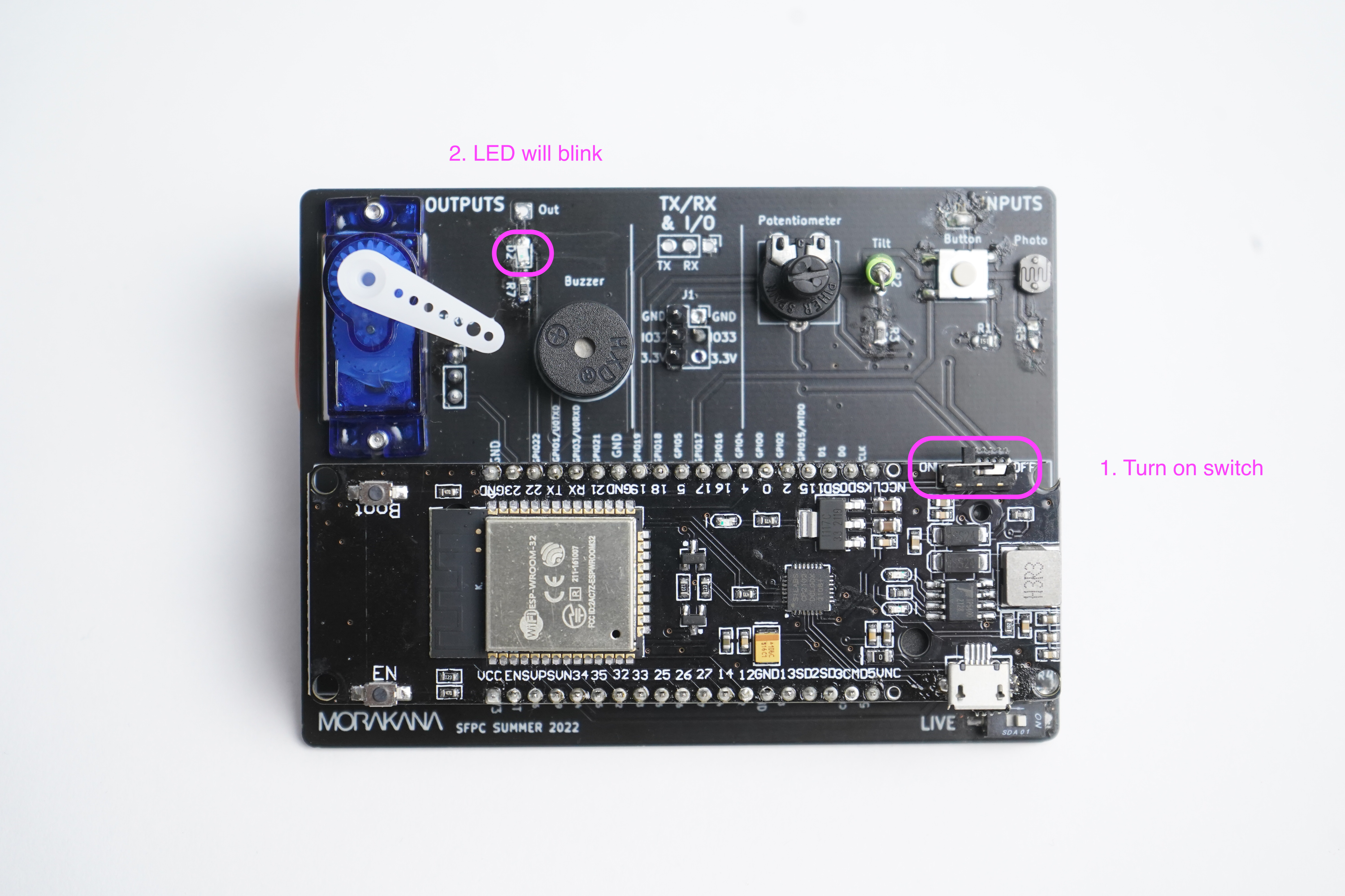
If after 15 seconds it wasn’t able to connect:
The name of the network will be ExperimentHardPerf_[random numbers]
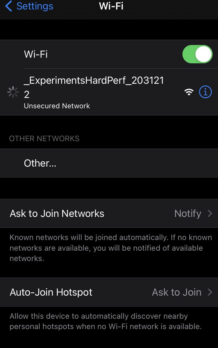
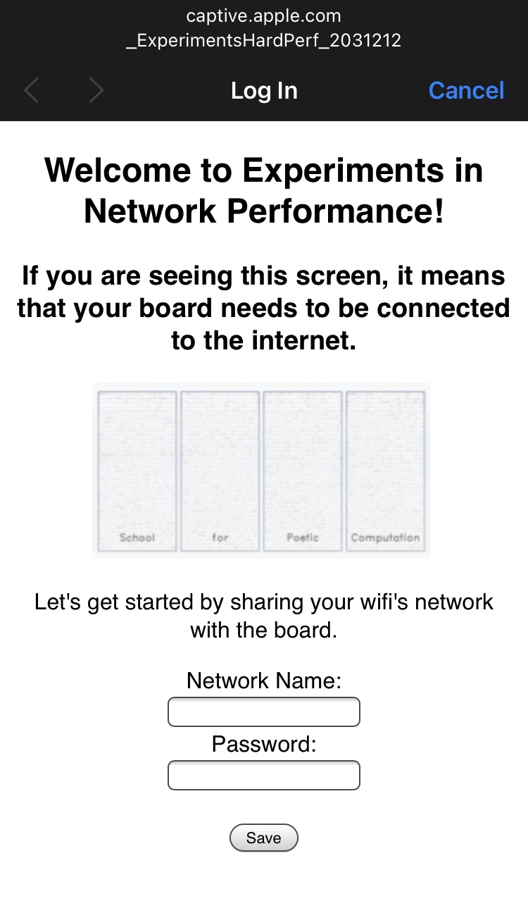
Note: watch out for upper/lower case
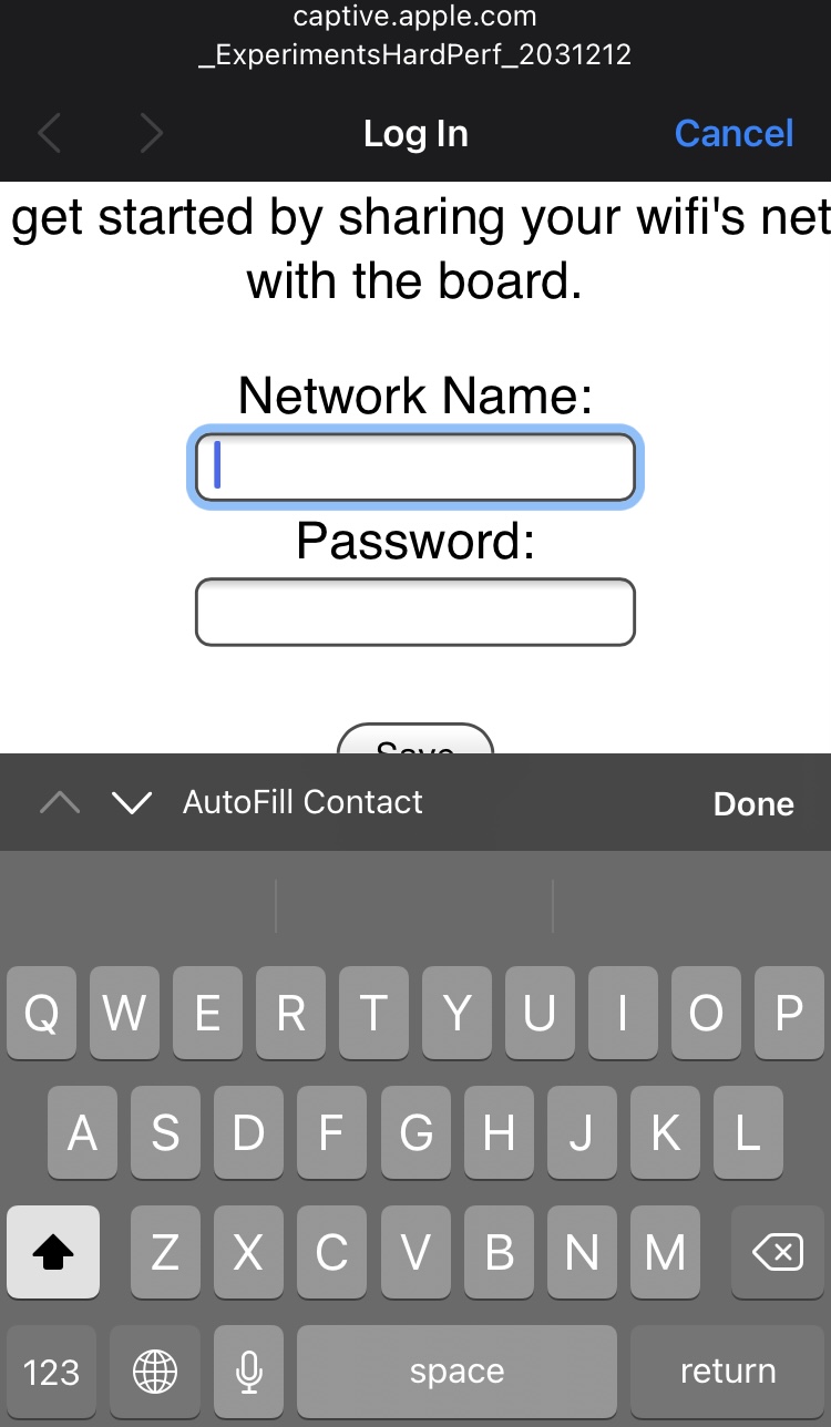
Note: watch out for upper/lower case
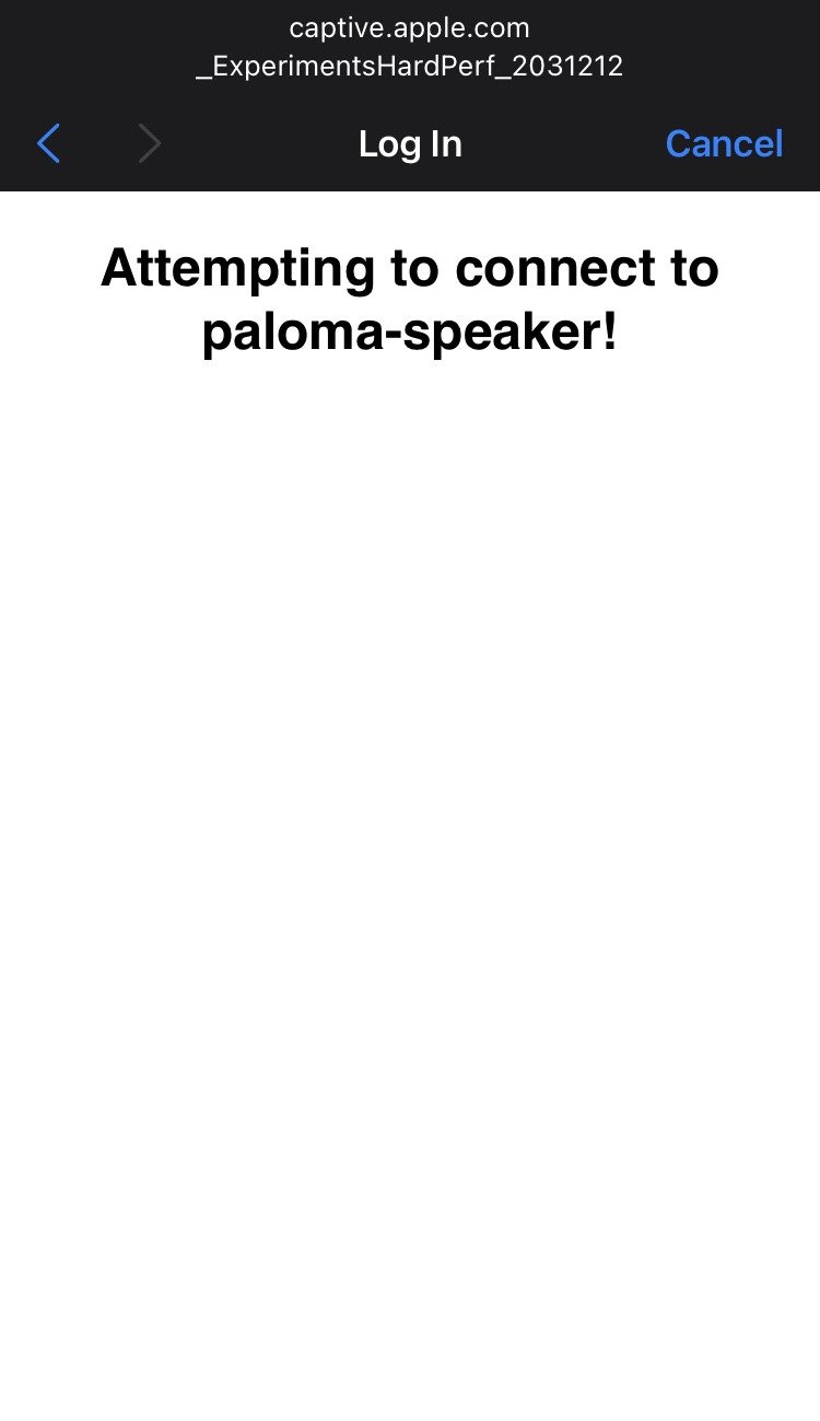
I turn it on but nothing happens, no beep, no flashing led.
Most likely, it’s out of battery, try charging it though the micro USB port
I turn the board on, and it beeps, then it beeps again, and again, and again…
This means that the board is constantly restarting, most likely it’s out of battery, try recharging the battery though it’s Micro USB port
I added my wifi credentials but doesn’t nothing happened.
Try restarting the board by turning it off and on again, the board should attempt to connect and if it still is not able, repeat steps 2-6.
Also, in order to save battery, it will only wait for 1minute before going back to sleep. It could be that it’s taking a bit long to add your wifi credentials.
I was able to connect before now it’s asking for my wifi credentials again
The board only has 15 seconds to successfully connect to wifi, after this it will create it’s own network. Sometimes, these 15 seconds are not enough time connect, no need to add you credentials again, you can restart the board and have it try again.
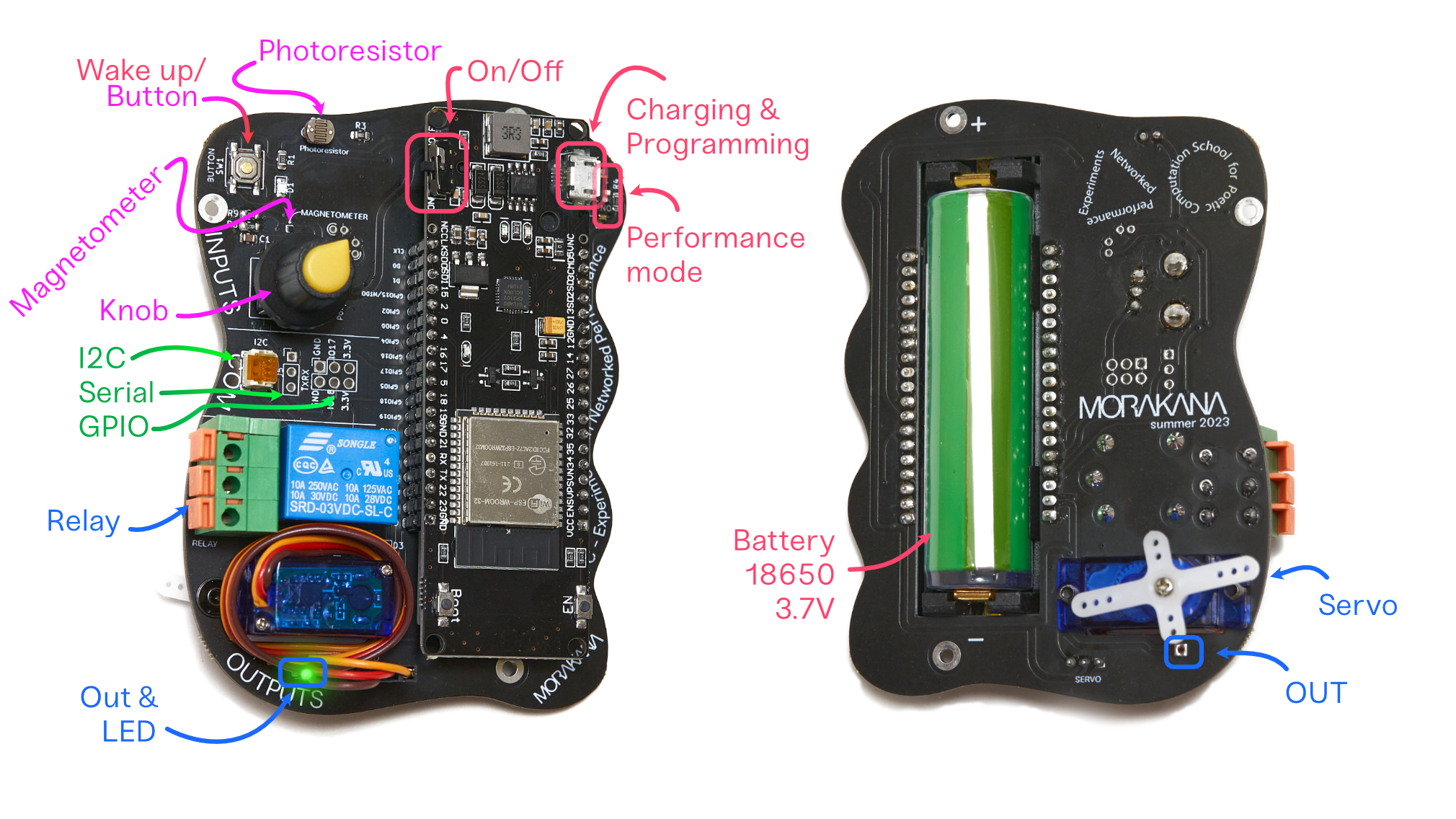
The board consists of the micocontroller (ESP32 dev board with a 18650 battery holder) and a series of inputs and outputs:
| Qty | Value | Footprint | References |
|---|---|---|---|
| 6 | 10K | Resistor_SMD:R_0805_2012Metric_Pad1.20x1.40mm_HandSolder | R3, R7, R10, R11, R14, R15 |
| 2 | 100nF | Capacitor_SMD:C_0805_2012Metric | C6, C7 |
| 2 | 10uF | Capacitor_SMD:C_0805_2012Metric | C1, C4 |
| 2 | 2.7K | Resistor_SMD:R_0805_2012Metric_Pad1.20x1.40mm_HandSolder | R12, R13 |
| 2 | 5.1K | Resistor_SMD:R_0805_2012Metric_Pad1.20x1.40mm_HandSolder | R8, R9 |
| 2 | BC817 | Package_TO_SOT_SMD:SOT-23 | Q2, Q3 |
| 2 | LED | LED_SMD:LED_0805_2012Metric_Pad1.15x1.40mm_HandSolder | D1, D2 |
| 2 | MountingHole | MountingHole:MountingHole_2.5mm_Pad_TopBottom | H1, H4 |
| 1 | 0.1uF | Capacitor_SMD:C_0805_2012Metric | C3 |
| 1 | 1K | Resistor_SMD:R_0805_2012Metric_Pad1.20x1.40mm_HandSolder | R6 |
| 1 | 1M | Resistor_SMD:R_0805_2012Metric_Pad1.20x1.40mm_HandSolder | R4 |
| 1 | 1N4148W | Diode_SMD:D_SOD-123 | D3 |
| 1 | 1uF | Capacitor_SMD:C_0805_2012Metric | C5 |
| 1 | 220 | Resistor_SMD:R_0805_2012Metric_Pad1.20x1.40mm_HandSolder | R5 |
| 1 | 220nF | Capacitor_SMD:C_0805_2012Metric | C2 |
| 1 | C475135 | spring_terminal:spring_terminal | J6 |
| 1 | CP2102N-Axx-xQFN28 | Package_DFN_QFN:QFN-28-1EP_5x5mm_P0.5mm_EP3.35x3.35mm | U4 |
| 1 | ESP32-DevKitC | Espressif:ESP32-Dev_Batt_18650 | U1 |
| 1 | FINDER-36.11 | Relay_THT:Relay_SPDT_Finder_36.11 | K1 |
| 1 | GND | Connector_Wire:SolderWire-0.5sqmm_1x01_D0.9mm_OD2.1mm | J7 |
| 1 | I2C | Connector_JST:JST_SH_SM04B-SRSS-TB_1x04-1MP_P1.00mm_Horizontal | J5 |
| 1 | LOGO | LOGO | G*** |
| 1 | LOGO | Graphics:MORAKANA_20mm_White | G*** |
| 1 | LSM303C | Package_LGA:LGA-12_2x2mm_P0.5mm | U3 |
| 1 | MIC5225-3.3YM5 | Package_TO_SOT_SMD:SOT-23-5 | U2 |
| 1 | MMBT3904 | Package_TO_SOT_SMD:SOT-23 | Q1 |
| 1 | OUT0 | Connector_Wire:SolderWire-0.5sqmm_1x01_D0.9mm_OD2.1mm | J4 |
| 1 | Photoresistor | Resistor_THT:R_Axial_DIN0204_L3.6mm_D1.6mm_P2.54mm_Vertical | R2 |
| 1 | Potentiometer | Potentiometer_THT:Potentiometer_Bourns_PTV09A-1_Single_Vertical | RV5K1 |
| 1 | R220 | Resistor_SMD:R_0805_2012Metric_Pad1.20x1.40mm_HandSolder | R1 |
| 1 | S15OT421 | Audio_Module:S15OT421 | MIC |
| 1 | SERVO | Connector_PinSocket_2.54mm:PinSocket_1x03_P2.54mm_Vertical | J2 |
| 1 | SW_DIP_x01 | Button_Switch_SMD:SW_DIP_SPSTx01_Slide_Omron_A6S-110x_W8.9mm_P2.54mm | SW2 |
| 1 | SW_DIP_x01 | Button_Switch_SMD:SW_Push_1P1T_NO_CK_KSC7xxJ | SW1 |
| 1 | TXRX | Connector_PinHeader_2.54mm:PinHeader_1x03_P2.54mm_Vertical | J3 |
| 1 | USB_C_Receptacle_USB2.0 | Connector_USB:USB_C_Receptacle_Amphenol_12401610E4-2A_CircularHoles | J8 |
| 1 | hookup | Connector_PinSocket_2.54mm:PinSocket_2x03_P2.54mm_Vertical | J1 |
It measures 76.3 × 105.1 mm and has 2 copper layers, 1.6 mm thick.
49 parts, built around the ESP32-DEVKITC-VE, LSM303C, MIC5225-3.3YM5 and BC817. The full list of its parts is on this page, with links to each part's symbol and footprint where PCBKit's library has them.
From the sebmorales/ENHP repository on GitHub, at the commit this page was made from: the board is NetworkedHardware_PCB_design/ENHP_eleklekha.kicad_pcb and its schematic NetworkedHardware_PCB_design/ENHP_eleklekha.kicad_sch. PCBKit opens the board in the browser, with nothing to install.
Its repository states no licence, so its author keeps all rights: ask sebmorales before reusing the design.

generationmake/TMF882xBreakout
Breakout board for the ams TMF8820, TMF8821 and TMF8828 multi-zone time-of-flight sensors

generationmake/TMF8801Breakout
Breakout board for the ams TMF8801 1D time-of-flight sensor


cnlohr/esp32_tracker
DO NOT USE THIS PROJECT - ESP32 Tracker with the TS4231
