


2 layers132.1 × 45.7 mm
IPoS
peterheinrich/InternetOverSpaghetti
Transmitting IP packages over a pair of spaghetti thus demonstrating how media independent IP really is.
42 parts342

 sebmate/MagicQuartz-TechDemo2
Turntable speedbox implementation for the MagicQuartz firmware
MagicQuartz Mega is an open-source printed circuit board by sebmate, from the sebmate/MagicQuartz-TechDemo repository on GitHub. It is a 2-layer board of 82.6 × 50.2 mm with 33 parts on 51 nets, routed with 198 tracks and 0 vias.
It is built around the LM358. Its parts include 9 resistors, 7 capacitors, 4 connectors, 4 switches and 2 ICs. It belongs with the power and robots and motor control boards of this library.
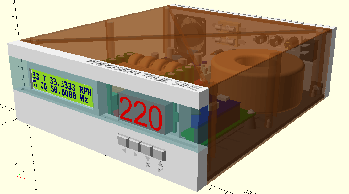
This repository contains an open source hardware design of a turntable speedbox that is capable of running the MagicQuartz firmware. The hardware design consists of two parts:
The speedbox implements an AC power inverter based on a class-D audio amplifier and a toroidal transformer to step-up the voltage. The speed of the record player is controlled by changing the generated AC frequency. This enables electronic switching between the standard record speeds (16, 33, 45, and 78 RPM) and real-time speed correction using an optical sensor. Note that this approach only works for turntables with AC motor. Optional voltage reduction can significantly reduce motor noise on synchronous motors.
The device supports the most important features of MagicQuartz version 1.1x, "Sparrow", including the "Advanced Power Management" (APM). However, it lacks standby for the LCD backlight and fans and it does not implement hardware-side pop supression.
The information and files in this repository are provided under the CERN-OHL-S v2 open source license (please click here for details).
In the hardware design presented here, great emphasis was put on safety. For example, the housing features active cooling and touch protection. It creates an IT network (Isolé Terre). The circuitry is equipped with safeguards against overcurrent and overvoltage (the latter with the LittleJimmy extension, see below). Finally, the MagicQuartz firmware implementes further safety measures in software (see documentation).
However, the main purpose of this repository is to provide an easily reproducible, simple hardware design to demonstrate the capabilities of the MagicQuartz firmware (this is why it is called "TechDemo"). The design has not been formally tested for electrical safety, electromagnetic compatibility (EMC), or fire safety. If you build and/or operate the device, you do so at your own risk. If you do not have sufficient knowledge in electronics, please do not attempt to build and/or operate the device. Also pay close attention to section 6 of the CERN-OHL-S v2 license and the safety considerations below. Devices manufactured based on this design may not be suitable for end users.
The following is a list of safety considerations that you should keep in mind:
The OpenSCAD file can be used to virtually explore the device and to 3D-print a physical enclosure.
Note: If the symbols on the front are not displayed correctly, the "Symbola" font has to be installed (Ubuntu package name: fonts-symbola).
The table below provides an overview of all 3D-printable parts in the 3D model along with some notes. Be aware that the printing time in total is around 22 hours (on an Ultimaker 2).
While the STL files are available in the release folder for your convenience, they can be generated easily in OpenSCAD. Set the variable render_components to false and change the value of the variable generate to the respective part number. Then press F5 to preview the part, F6 to render the part, and F7 to export the STL file. Note that the rendering process may take a considerable amount of time, even on fast computers. Also note that the generated objects are already properly oriented for printing.
I had some problems printing with Cura versions 5.1.1 to 5.3.0, especially with the "Back" part. The slicer created some signifcant artifacts and did not handle the text as expected (the last layer under the text was not printed as expected). I went back to 4.13.1.
In addition to the table below:
| Part Nr. | Name | Suggested Color | Notes / Exceptions |
|---|---|---|---|
| 1 | Bottom Plate | Black | May be printed without "tree" support. |
| 1 | Bottom Plate (Material Saver) | Black | Saves some filament, but is less sturdy. May be printed without "tree" support. |
| 2 | Front Lower Part | White | Set "Support X/Y Distance" to 1.6 mm to prevent the slicer from creating support in the air inlet. |
| 3 | Front Center Part | Transparent | Use the "lightning" infill pattern to create a nice "quartz-like" appearance. |
| 4 | Front Upper Part | White | |
| 5 | Cover | Brown | Print this variant if you do not plan to apply decorative foil. |
| 5 | Cover (Material Saver) | (Any) | If decorative foil does not adhere properly to the edges, slightly sand down the surfaces at the edges. |
| 6 | Foot (Print 4x) | Silver | May be printed without "brim". |
| 7 | Voltmeter Cover | As Front | |
| 8 | Button Assembly | Silver | Print with 0.1 mm or less to improve strength, do not use adhesion support (brim). Enable ironing on top layer. |
| 9 | Back | White | |
| 10 | Dummy sockets | As Back | Print without "brim". |
| 11 | Optical Sensor Case | Black |
The components to be used should be easily identifiable from the OpenSCAD and KiCad projects. For components where this is not immediately obvious, here are some details:
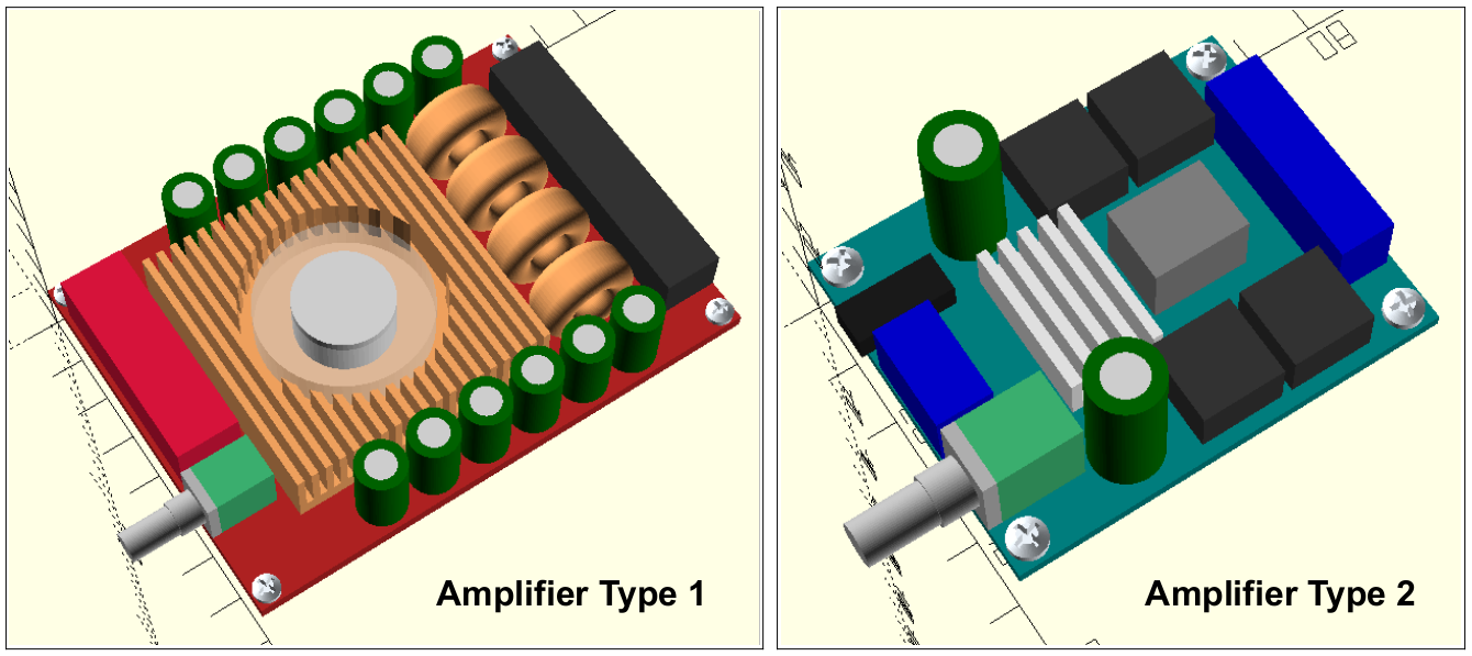
This repository also contains an electronic circuit for a mainboard. The PCB was designed for rapid prototyping and can be produced single-sided, e.g. with a small CNC or by etching. However, an optional top copper layer can be used to improve shielding. Of course, the PCB can also be manufactured by any PCB manufacturer.
The mainboard is build around the "MEGA 2560 PRO" board (denoted U1 in the schematic). To the author's knowledge, this board was originally developed by RobotDyn. Unfortunately, it seems to be no longer available, but re-makes by other companies are widely available. Click here for an archived version of RobotDyn's webpage.
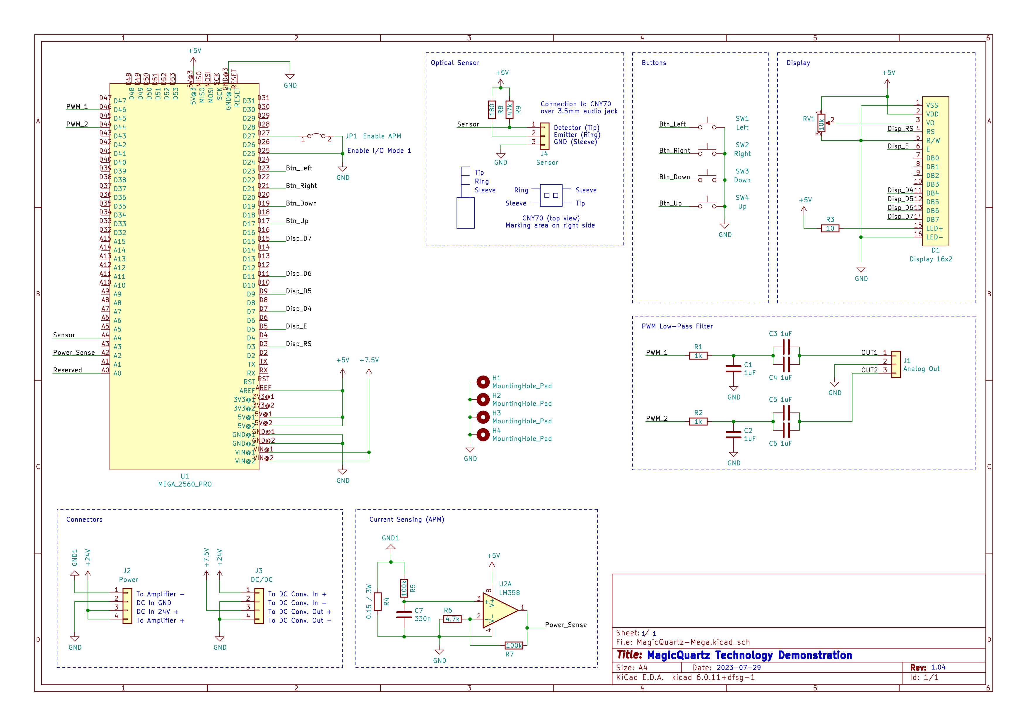
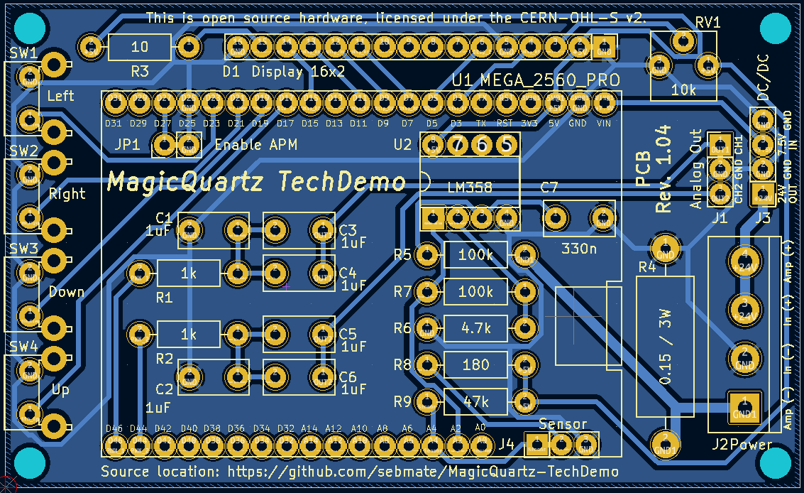
The electronic circuit is very simple and should be self-explanatory. However, the following points explain some special aspects:
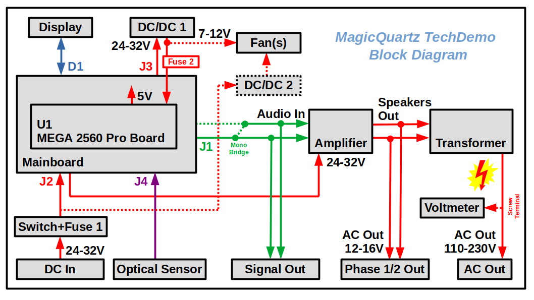
Here is a block diagram that provides an overview of all internal connections:
The "MEGA 2560 PRO" board may use an "AMS1117" 5V voltage regulator of questionable quality (see this interesting blog post). The regulator may fail with a full or partial internal short and pass the input voltage (7.5V) to the rest of the circuit. This may not only damage the other components (including the ATmega2560), it may also increase the level of the sinusoidal signal generated. As a result, the inverter may generate excessive voltage and damage the turntable.
The problem can be overcome by replacing the AMS1117 by another "1117"-type regulator from a renowned manufacturer, such as the LM1117 by Texas Instruments or the TS1117 by Taiwan Semiconductor. Of course, the part should be purchased from a reputable electronics distributor. The old regulator can be desoldered easily by applying excess fresh solder to its three pins, heating everything up, and then wiping it away with the soldering iron.
Depending on the regulator, additional 10uF tantalum capacitors may need to be added to the input and output of the regulator (see data sheet). Such a modification based on an TS1117 is shown in this image: images/TS1117-Modification.jpg. Notice the two new yellow tantalum capacitors and the additional fuse (see below). Carefully observe the polarity of the capacitors!
A more sophisticated (and probably over-the-top) solution is adding a crowbar circuit and a fuse to the design. The crowbar circuit can be supplied as a small piggyback board for the "MEGA 2560 PRO". Such an add-on is available here: https://github.com/sebmate/LittleJimmy. Here is a picture of it mounted in the speedbox: images/LittleJimmy.jpg.
The fuse is actually only needed for the crowbar circuit, but there is nothing wrong with adding it in general. The above block diagram and the rear panel of the enclosure have already been extended to incorporate this fuse. As described above, as the circuit is drawing about 100mA at 7.5V, using a 125mA fast-acting fuse is reasonable.
These inexpensive step-down boards probably don't use original LM2596S ICs (see this link for more information). So far, however, I have had no issues with these. The above described crowbar circuit, when installed on the "MEGA 2560 PRO" board, also provides some protection against a possible failure of such an LM2596S DC/DC converter board.
Parts lists are available in the directory parts-lists.
One of the lists is for the German electronics distributor Reichelt. This list can also be accessed directly via this link: https://www.reichelt.de/my/2038407. This list also contains alternative parts that are not essential. The list should therefore not be ordered blindly. Please note that I am not affiliated with Reichelt and am only providing this list for your convenience. The parts may be available from other vendors at a lower price.
images folder. Note that these do not yet show the latest revision with the LittleJimmy circuit and the second fuse.The following steps describe how to initially setup the device:
WaveForm), set this to 2.VoltageMtOn), the documentation says that the steps depend on whether the inverter installed in the speedbox has a level control or not. It has: it's the volume control of the amplifier. Proceed as described in the documentation: Set VoltageMtOn to 1, then slowly and carefully turn up the volume control of the amplifier until the desired voltage (e.g., 220V) is reached. If the amplifier switches into the protection state, try again.RampingSpeed value and then restarting the inverter. If it does not work and if the measured current values in the firmware are on the lower end of the measuring range (which is from 0 to 1023), you may replace R7 with a higher value resistor, such as 470 kOhm.| Qty | Value | Footprint | References |
|---|---|---|---|
| 6 | 1uF | Capacitor_THT:C_Rect_L7.2mm_W3.5mm_P5.00mm_FKS2_FKP2_MKS2_MKP2 | C1, C2, C3, C4, C5, C6 |
| 4 | MountingHole_Pad | MountingHole:MountingHole_3.2mm_M3 | H1, H2, H3, H4 |
| 2 | 100k | Resistor_THT:R_Axial_DIN0207_L6.3mm_D2.5mm_P10.16mm_Horizontal | R5, R7 |
| 2 | 1k | Resistor_THT:R_Axial_DIN0207_L6.3mm_D2.5mm_P10.16mm_Horizontal | R1, R2 |
| 1 | 0.15 / 3W | Resistor_THT:R_Axial_DIN0614_L14.3mm_D5.7mm_P20.32mm_Horizontal | R4 |
| 1 | 10 | Resistor_THT:R_Axial_DIN0207_L6.3mm_D2.5mm_P10.16mm_Horizontal | R3 |
| 1 | 10k | Potentiometer_THT:Potentiometer_Vishay_T73YP_Vertical | RV1 |
| 1 | 180 | Resistor_THT:R_Axial_DIN0207_L6.3mm_D2.5mm_P10.16mm_Horizontal | R8 |
| 1 | 330n | Capacitor_THT:C_Rect_L7.2mm_W3.5mm_P5.00mm_FKS2_FKP2_MKS2_MKP2 | C7 |
| 1 | 4.7k | Resistor_THT:R_Axial_DIN0207_L6.3mm_D2.5mm_P10.16mm_Horizontal | R6 |
| 1 | 47k | Resistor_THT:R_Axial_DIN0207_L6.3mm_D2.5mm_P10.16mm_Horizontal | R9 |
| 1 | Analog Out | Connector_PinHeader_2.54mm:PinHeader_1x03_P2.54mm_Vertical | J1 |
| 1 | DC/DC | Connector_PinHeader_2.54mm:PinHeader_1x04_P2.54mm_Vertical | J3 |
| 1 | Display 16x2 | Connector_PinHeader_2.54mm:PinHeader_1x16_P2.54mm_Vertical | D1 |
| 1 | Down | Button_Switch_THT:SW_Tactile_SPST_Angled_PTS645Vx83-2LFS | SW3 |
| 1 | Enable APM | Connector_PinHeader_2.54mm:PinHeader_1x02_P2.54mm_Vertical | JP1 |
| 1 | LM358 | Package_DIP:DIP-8_W7.62mm_Socket | U2 |
| 1 | Left | Button_Switch_THT:SW_Tactile_SPST_Angled_PTS645Vx83-2LFS | SW1 |
| 1 | MEGA_2560_PRO | MagicQuartzParts:MEGA2560PRO-Reduced | U1 |
| 1 | Power | TerminalBlock:TerminalBlock_bornier-4_P5.08mm | J2 |
| 1 | Right | Button_Switch_THT:SW_Tactile_SPST_Angled_PTS645Vx83-2LFS | SW2 |
| 1 | Sensor | Connector_PinHeader_2.54mm:PinHeader_1x03_P2.54mm_Vertical | J4 |
| 1 | Up | Button_Switch_THT:SW_Tactile_SPST_Angled_PTS645Vx83-2LFS | SW4 |
It measures 82.6 × 50.2 mm and has 2 copper layers, 1.6 mm thick.
33 parts, built around the LM358. The full list of its parts is on this page, with links to each part's symbol and footprint where PCBKit's library has them.
From the sebmate/MagicQuartz-TechDemo repository on GitHub, at the commit this page was made from: the board is src/KiCad/MagicQuartz-Mega/MagicQuartz-Mega.kicad_pcb and its schematic src/KiCad/MagicQuartz-Mega/MagicQuartz-Mega.kicad_sch. PCBKit opens the board in the browser, with nothing to install.
Its repository states no licence, so its author keeps all rights: ask sebmate before reusing the design.
peterheinrich/InternetOverSpaghetti
Transmitting IP packages over a pair of spaghetti thus demonstrating how media independent IP really is.

zmaker/arduino_cookbook
gli sketch del nuovo progetto Arduino Cookbook e dei video di YouTube

profdc9/RFBitBanger
A QRP digital transceiver created from readily available parts for off-the-grid maintenance


tvlad1234/pillScopePlus
Oscilloscope based around the STM32F401 Black Pill and a color LCD screen


starlightk7/OpenSFC
OSHW Reproduction Parts related to the Super Famicom / Super Nintendo game console
