2 layers24.5 × 15.2 mm

 sebasdv/pikocore_gamepad
Fork of pikocore ported to run on the Waveshare RP2350-PiZero + GamePi13 handheld — full-color LCD dashboard, 12-button menu, and save/load state on a lo-fi sampler that was originally knob-only.
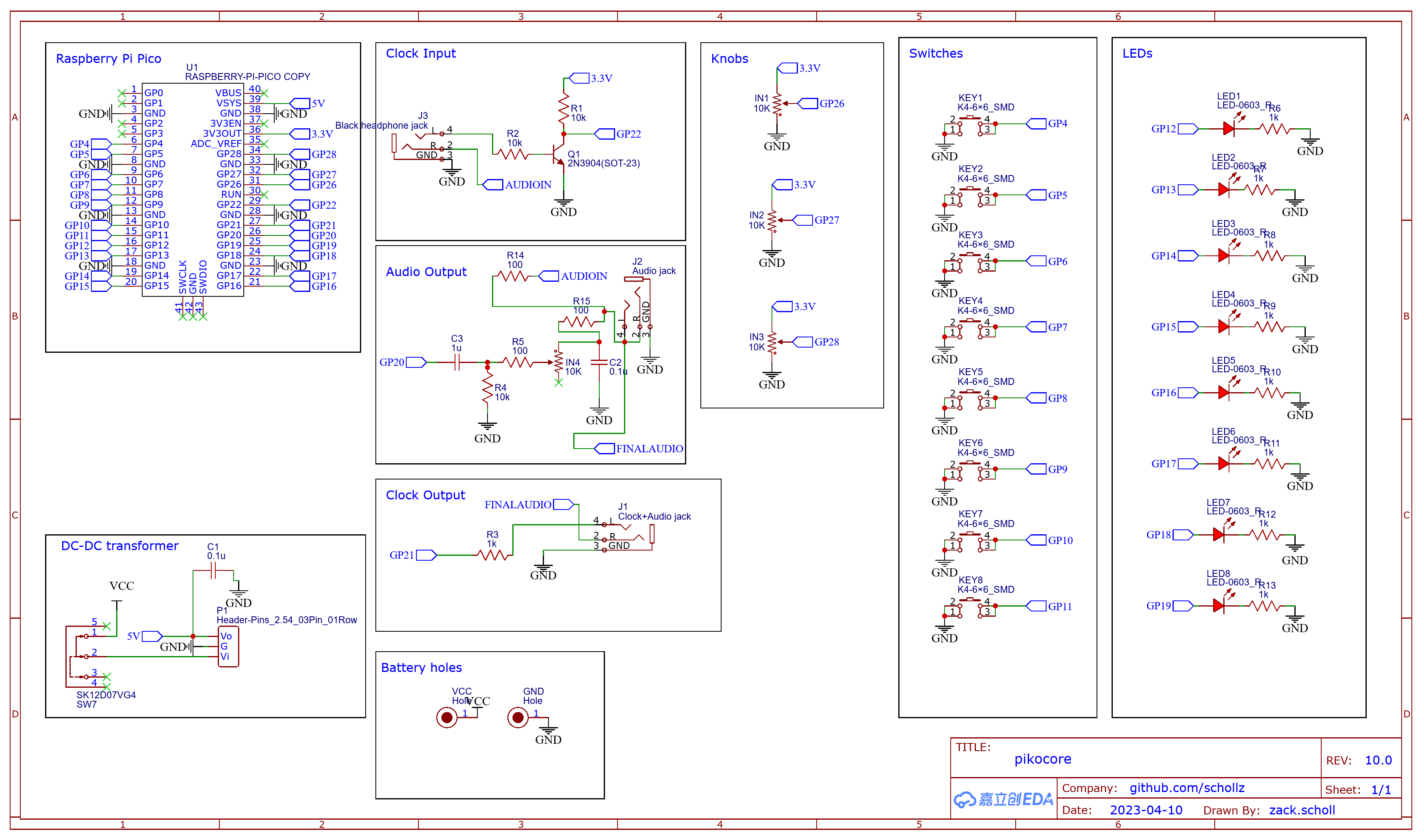
Pikocore gamepad is an open-source printed circuit board by sebasdv, from the sebasdv/pikocore_gamepad repository on GitHub, published under the MIT licence. It is a 4-layer board of 100 × 60 mm with 76 parts on 76 nets, routed with 656 tracks and 134 vias.
It is built around the PT2308-S, H11L1SR2M and SN74LVC1G17DCKR, with the 1N4148W among its other parts. Its parts include 27 capacitors, 21 resistors, 13 switches, 7 ICs and 5 connectors. It belongs with the keyboards and input and lEDs and displays boards and the RP2350 boards of this library.



A community port of pikocore, the hackable open-source lo-fi sampler, to run on the Waveshare RP2350-PiZero paired with the GamePi13 handheld HAT — trading the original's bare-bones potentiometer interface for a 240×240 color LCD dashboard and a 12-button game-console layout.
This is an independent fork, not officially affiliated with the original pikocore project or with Waveshare.
web/) to build .pikobank files
from your own samples and load them straight over USB..pikobank browsing exists in the codebase but ships disabled by
default behind a build flag (PIKO_GAMEPI13_SD) — see
GAMEPI13-INTERFACE.md for why.All of the original pikocore's audio engine — sample playback, slicing, retrigger/ stutter, probability-driven jump/gate/reverse/tunnel effects, filter, timestretch — is untouched; this port only adds the screen, the button-driven menu, and the persistence layer around it.
PIKO_GAMEPI13_SD=ON.mkdir -p build-gamepi && cd build-gamepi
cmake -DPICO_SDK_PATH=../pico-sdk -DPIKO_GAMEPI13=ON ..
make -j4Flash build-gamepi/pikocore.uf2 (hold BOOTSEL while plugging in USB).
The original, unmodified stock-hardware build (potentiometers, no LCD) still works
from the same tree — see the upstream build instructions below.
The custom carrier-PCB variant (RP2350-Plus + I2S DAC) builds with
-DPIKO_GAMEPAD=ON instead — see hardware/pikocore_gamepad/README.md.
Use the loader at sebasdv.github.io/pikocore_gamepad — no local server needed, just open it in a browser that supports Web Serial (Chrome/Edge).
Build a bank from your own samples and either load it straight over USB, or use
the "Download bank" button to produce a .pikobank file for a microSD card (if
built with SD support).
To run the loader locally instead (e.g. for development):
cd web && npm install && npm run dev| Control | Function |
|---|---|
| D-pad + Y/X/B/A | pikocore's 8 music buttons |
| Select | cycle parameter mode (tap), or hold + a music button to jump directly to that mode |
| L / R | decrease/increase the active parameter (Function A); hold to repeat |
| Start (tap) | mute / start-stop |
| Start (hold) + L/R | edit Function B instead of Function A |
| Up+Down+B+A | reset FX (filter, distortion, all probabilities) |
| Down+Left+X+B | toggle clock lock |
Full mode table, per-button behavior, retrigger mechanics, and every hardware finding from bring-up are in GAMEPI13-INTERFACE.md (Spanish). Build/flash/pinout quick reference: README-GAMEPI13.md (Spanish).
For the original potentiometer-based hardware, schematic, BOM, and firmware releases, see the upstream project:
SAMPLE_RATE=31000 make(make build2 if you're on a 2MB Pico; the default targets 16MB.) See the
upstream README for the full prerequisites list (make prereqs).
This port stands entirely on other people's work:
_core lineage.src/gamepi13/lcd/) and board files
(RP2350-PiZero/, Gamepi13-RP2040-Demo/) are adapted from Waveshare's own demo
code for this hardware.SDBlockDevice, and an SDIO
driver derived from ZuluSCSI-firmware.doth/WS2812.cpp), inherited from upstream pikocore under its original
BSD-3-Clause / GPL-3 dual attribution (see the file header).doth/onewiremidi.h), MIT licensed, inherited from
upstream pikocore.MIDI_IN_ENABLED build option targets.MIT — see LICENSE. Some vendored third-party components carry their
own licenses; see the file headers under doth/ and the Acknowledgments section
above.
| Qty | Value | Footprint | References |
|---|---|---|---|
| 8 | 100nF | Capacitor_SMD:C_0603_1608Metric | C7, C10, C11, C13, C15, C20, C27, C56 |
| 6 | 10k | Resistor_SMD:R_0603_1608Metric | R9, R10, R12, R14, R16, R17 |
| 5 | 10uF | Capacitor_SMD:C_0603_1608Metric | C4, C12, C14, C16, C29 |
| 4 | 1uF | Capacitor_SMD:C_0603_1608Metric | C21, C22, C25, C26 |
| 4 | 4.7k | Resistor_SMD:R_0603_1608Metric | R18, R19, R20, R43 |
| 3 | 22uF | Capacitor_SMD:C_0805_2012Metric | C5, C6, C28 |
| 2 | 2.2nF | Capacitor_SMD:C_0603_1608Metric | C17, C18 |
| 2 | 2.2uF | Capacitor_SMD:C_0603_1608Metric | C8, C9 |
| 2 | 2.2uH | Inductor_SMD:L_1210_3225Metric | L1, L2 |
| 2 | 20k | Resistor_SMD:R_0603_1608Metric | R11, R13 |
| 2 | 470R | Resistor_SMD:R_0603_1608Metric | R7, R8 |
| 2 | 470uF | Capacitor_SMD:CP_Elec_6.3x5.4 | C23, C24 |
| 1 | 100k | Resistor_SMD:R_0603_1608Metric | R6 |
| 1 | 100uF | Capacitor_SMD:C_1206_3216Metric | C19 |
| 1 | 10R | Resistor_SMD:R_0603_1608Metric | R41 |
| 1 | 1N4148W | Diode_SMD:D_SOD-123 | D3 |
| 1 | 200k | Resistor_SMD:R_0603_1608Metric | R4 |
| 1 | 220R | Resistor_SMD:R_0603_1608Metric | R42 |
| 1 | 27k | Resistor_SMD:R_0603_1608Metric | R5 |
| 1 | 33R | Resistor_SMD:R_0603_1608Metric | R40 |
| 1 | 47k | Resistor_SMD:R_0603_1608Metric | R15 |
| 1 | BTN_A | Button_Switch_THT:SW_PUSH_6mm | SW7 |
| 1 | BTN_B | Button_Switch_THT:SW_PUSH_6mm | SW8 |
| 1 | BTN_L | Button_Switch_THT:SW_Tactile_SPST_Angled_PTS645Vx39-2LFS | SW9 |
| 1 | BTN_R | Button_Switch_THT:SW_Tactile_SPST_Angled_PTS645Vx39-2LFS | SW10 |
| 1 | BTN_SELECT | Button_Switch_THT:SW_PUSH_6mm | SW12 |
| 1 | BTN_START | Button_Switch_THT:SW_PUSH_6mm | SW11 |
| 1 | BTN_X | Button_Switch_THT:SW_PUSH_6mm | SW5 |
| 1 | BTN_Y | Button_Switch_THT:SW_PUSH_6mm | SW6 |
| 1 | DPAD_DOWN | Button_Switch_THT:SW_PUSH_6mm | SW2 |
| 1 | DPAD_LEFT | Button_Switch_THT:SW_PUSH_6mm | SW3 |
| 1 | DPAD_RIGHT | Button_Switch_THT:SW_PUSH_6mm | SW4 |
| 1 | DPAD_UP | Button_Switch_THT:SW_PUSH_6mm | SW1 |
| 1 | H11L1SR2M | Package_DIP:SMDIP-6_W7.62mm | U10 |
| 1 | MIDI IN | Connector_Audio:Jack_3.5mm_CUI_SJ1-3535NG_Horizontal | J6 |
| 1 | MIDI OUT | Connector_Audio:Jack_3.5mm_CUI_SJ1-3535NG_Horizontal | J7 |
| 1 | PAM8302A | gamesetup_lcsc:MSOP-8_L3.0-W3.0-P0.65-LS5.0-BL | U4 |
| 1 | PCM5102APWR | gamesetup_lcsc:TSSOP-20_L6.5-W4.4-P0.65-LS6.4-BL | U5 |
| 1 | PHONES | Connector_Audio:Jack_3.5mm_CUI_SJ1-3535NG_Horizontal | J1 |
| 1 | PT2308-S | Package_SO:SOIC-8_3.9x4.9mm_P1.27mm | U3 |
| 1 | PWR | gamesetup_lcsc:SW-TH_SK12D07VG3 | SW15 |
| 1 | RP2350-Plus-16MB | gamesetup_fp:RP2350-Plus_Castellated | U1 |
| 1 | SN74LVC1G17DCKR | Package_TO_SOT_SMD:SOT-353_SC-70-5 | U9 |
| 1 | SPEAKER 8R | Connector_JST:JST_PH_B2B-PH-K_1x02_P2.00mm_Vertical | J5 |
| 1 | ST7789_240x240 | gamesetup_fp:LCD_ST7789_240x240_7P | J4 |
| 1 | TPS61023DRLR | Package_TO_SOT_SMD:SOT-563 | U2 |


shorepine/tulipcc
The Tulip Creative Computer and AMYboard - portable Python synthesizers

Eight4aWish/eurorack_electronics
Analogue designs and breadboard layouts: the Dual Pingable LPG, and the board behind Boy.

antoinevg/tiliqua
A powerful, hackable FPGA-based audio multitool for Eurorack.


ErichZimmer/OpenSync
An open source synchronizer for velocimetry of fluids.
It measures 100 × 60 mm and has 4 copper layers, 1.6 mm thick.
76 parts, built around the PT2308-S, H11L1SR2M, SN74LVC1G17DCKR and 1N4148W. The full list of its parts is on this page, with links to each part's symbol and footprint where PCBKit's library has them.
From the sebasdv/pikocore_gamepad repository on GitHub, at the commit this page was made from: the board is hardware/pikocore_gamepad/pcb/pikocore_gamepad.kicad_pcb and its schematic hardware/pikocore_gamepad/pcb/01_alimentacion.kicad_sch. PCBKit opens the board in the browser, with nothing to install.
Its repository publishes it under the MIT licence: you may reuse it on that licence's terms (keep the author's notice, and for a copyleft licence share your changes alike).