
2 layers20.5 × 24.8 mm

A simple through-hole PCB that pairs an ESP32-S3 Super Mini with a SN74AHCT125N quad bus buffer to shift 3.3V GPIO signals up to 5V logic — designed for driving WS2812B/SK6812 LED strips with Hyperk / HyperHDR ambilight…
Layouts is an open-source printed circuit board by seanuleh, from the seanuleh/supermini-level-shifter repository on GitHub. It is a 2-layer board of 44.5 × 25.5 mm with 8 parts on 24 nets, routed with 49 tracks and 0 vias.
Its parts include 4 connectors, 2 resistors, 1 capacitor and 1 IC.
A simple through-hole PCB that pairs an ESP32-S3 Super Mini with a SN74AHCT125N quad bus buffer to shift 3.3V GPIO signals up to 5V logic — designed for driving WS2812B/SK6812 LED strips with Hyperk / HyperHDR ambilight setups.
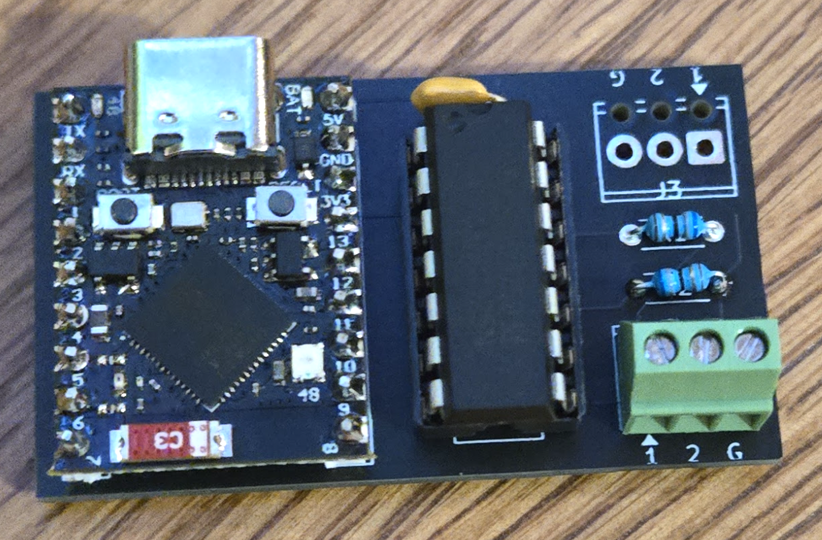 | 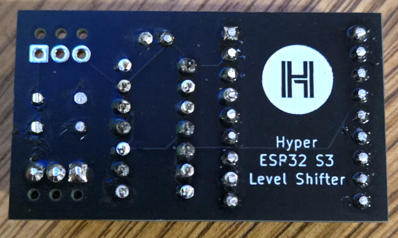 |
| Front | Back |
Download Gerbers (ZIP) — ready for JLCPCB / PCBWay (order bare PCB only)
Both terminals are electrically identical:
| Pin | Signal | Description |
|---|---|---|
| 1 | DATA1 | GP1 level-shifted (5V logic) — LED segment 1 |
| 2 | DATA2 | GP2 level-shifted (5V logic) — LED segment 2 |
| 3 | GND | Ground reference |
Power (5V) for the LED strips should come from a dedicated 5V supply, not the ESP32.
ESP32 GP1 (3.3V) → SN74AHCT125N 1A → 1Y → 68Ω → Terminal pin 1
ESP32 GP2 (3.3V) → SN74AHCT125N 2A → 2Y → 68Ω → Terminal pin 2
ESP32 GND ──────────────────────────────────────→ Terminal pin 3
ESP32 5V ──────────────────────────────────────→ IC VCC (pin 14)All parts are hand-soldered. No JLCPCB assembly required — order the bare PCB only.
| Ref | Part | Notes |
|---|---|---|
| J1, J2 | 1×9 female 2.54mm pin header | 2× required |
| U1 | SN74AHCT125N | DIP-14, e.g. LCSC C5907 |
| — | DIP-14 IC socket | Order separately |
| J3, J4 | 3-pin 2.54mm screw terminal | e.g. KF128-2.54-3P, Phoenix MPT-0.5/3-2.54 |
| R1, R2 | 68Ω 1/8W axial resistor | Any 62–100Ω 1/8W axial |
| C1 | 100nF ceramic disc capacitor | 50V, 2.5mm pitch |
Built with atopile 0.15.x.
ato.yaml                        # Build config
elec/src/
  level_shifter.ato             # Top-level module
  esp32s3_super_mini.ato        # ESP32 socket module
  parts/
    Header1x9F/                 # 1×9 female header
    SN74AHCT125N/               # DIP-14 quad buffer
    ScrewTerminal_2.54_3P/      # 3-pin screw terminal
    Resistor_TH_68R/            # 68Ω axial resistor
    Capacitor_TH_100nF/         # 100nF ceramic disc cap
elec/layouts/default/ # KiCAD PCB layout| Qty | Value | Footprint | References |
|---|---|---|---|
| 2 | Resistor_TH_68R:R_Axial_DIN0204_L3.6mm_D1.6mm_P5.08mm_Horizontal | R1, R2 | |
| 2 | Header1x9F:PinSocket_1x09_P2.54mm_Vertical | J1, J2 | |
| 2 | ScrewTerminal_2.54_3P:TerminalBlock_Phoenix_MPT-0,5-3-2.54_1x03_P2.54mm_Horizontal | J3, J4 | |
| 1 | SN74AHCT125N:DIP-14_W7.62mm | U1 | |
| 1 | Capacitor_TH_100nF:C_Disc_D3.0mm_W1.6mm_P2.50mm | C1 |
It measures 44.5 × 25.5 mm and has 2 copper layers, 1.6 mm thick.
8 parts. The full list of its parts is on this page, with links to each part's symbol and footprint where PCBKit's library has them.
From the seanuleh/supermini-level-shifter repository on GitHub, at the commit this page was made from: the board is elec/layouts/default/default.kicad_pcb. PCBKit opens the board in the browser, with nothing to install.
Its repository states no licence, so its author keeps all rights: ask seanuleh before reusing the design.

joeycastillo/Sensor-Watch
A board replacement for the classic Casio F-91W wristwatch

rusefi/rusefi
rusefi - GPL internal combustion engine control unit

hoglet67/RGBtoHDMI
Bare-metal Raspberry Pi project that provides pixel-perfect sampling of Retro Computer RGB/YUV video and conversion to HDMI

shanteacontrols/OpenDeck
A platform for building interactive control and sensing devices using MIDI and OSC built with Zephyr RTOS.

hackclub/OnBoard
💡 Join 1,000 teenagers and make your first PCB with a $100 grant!

dangiu/PicoMemcard
Emulating PSX Memory Card (or controller) using a Raspberry Pi Pico

OLIMEX/DIY-LAPTOP
Do It Yourself Open Source Hardware and Software Modular Hacker's Friendly Laptop