6 layers160 × 100 mm
DIG Card
scular-HCC/DualLaserPDHDriver
Dual laster Pound-Dreaver-Hall driver setup. 1550 nm DFBs. Q=10^-5. Less than 20 GHz difference
208 parts

 scular-HCC/DualLaserPDHDriver
Dual laster Pound-Dreaver-Hall driver setup. 1550 nm DFBs. Q=10^-5. Less than 20 GHz difference
Laser driver v3 Power is an open-source printed circuit board by scular-HCC, from the scular-HCC/DualLaserPDHDriver repository on GitHub. It is a 2-layer board of 261.3 × 165.2 mm with 280 parts on 156 nets, routed with 823 tracks and 265 vias.
It is built around the LM339, MMBT3904 and 1N4742A, with the 1N4148W, IRF540NPBF and IRF9540NPBF among its other parts. Its parts include 99 resistors, 90 capacitors, 22 diodes, 17 transistors and 14 ICs.


A precision two-channel controller for 1550 nm DFB butterfly lasers — a differential optical thermometer built as a 3U Eurocard instrument.
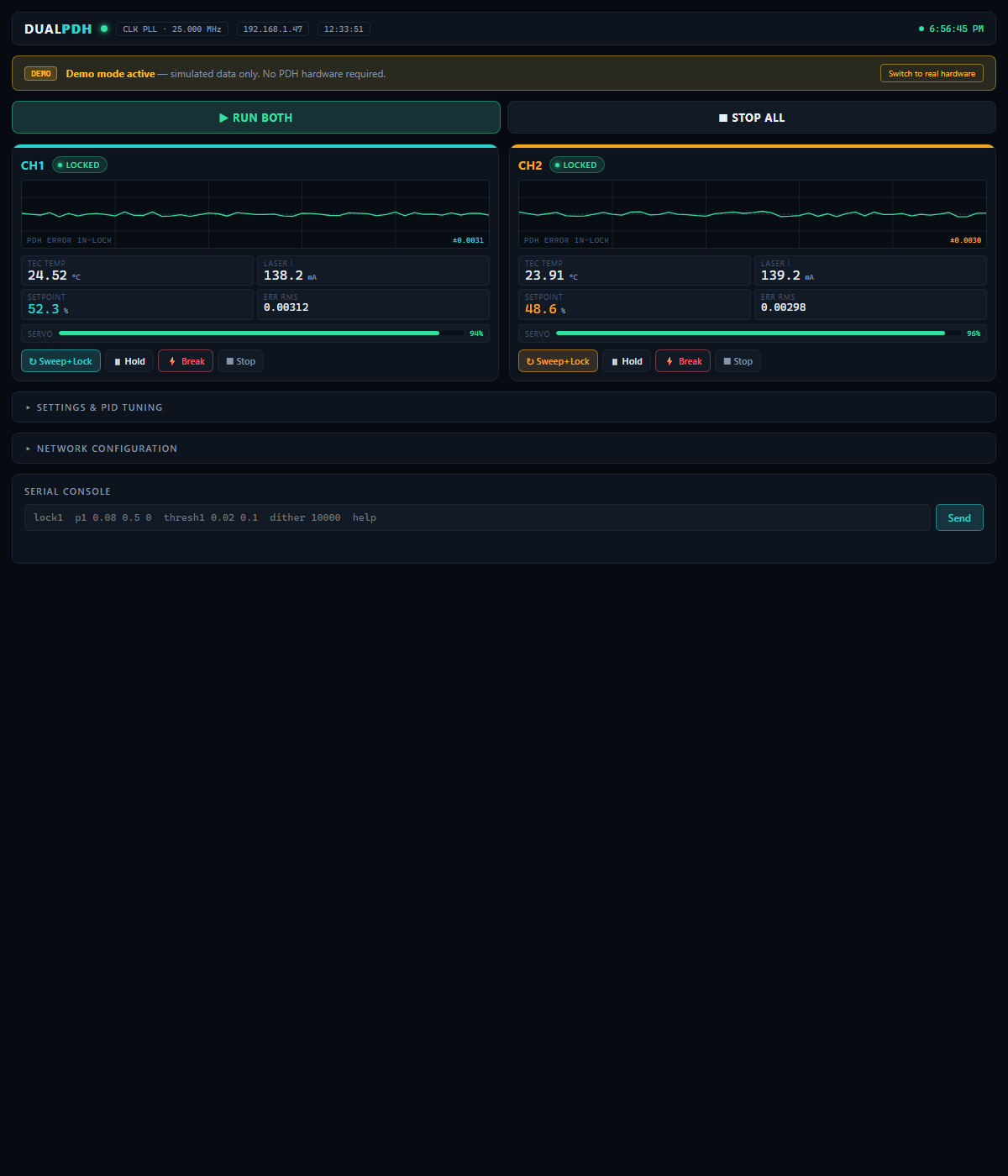
Each channel provides low-noise constant-current laser drive, a bipolar linear TEC temperature controller, RF frequency modulation, and a synchronous-demodulation Pound–Drever–Hall lock that holds the laser to the side of an optical resonance. Lasers A and B lock to their own fringe of a shared reference cavity; the beat frequency between them, Δν = S·(T_B − T_A) with S ≈ 2 GHz/K, is a ratiometric measurement in which slow common-mode drift cancels.
| 2× | 1550 nm DFB laser channels |
| ≈2 GHz/K | beat sensitivity |
| 4–40 nK | 60 s stability (equivalent-kelvin Allan deviation) |
| ±2.5 A | bipolar linear TEC per channel |
| 8-slot | 3U passive backplane, card-based architecture |
The RF analog-derivative lock this hardware runs targets the ≈4–11 nK regime, limited primarily by the laser's residual amplitude modulation (RAM), not by the electronics.
This is a mains-powered Class 3B/4 laser instrument. Before working on it, read Section 02 of the User Manual. In brief:
The instrument is a set of interchangeable cards on a passive 3U backplane, each in a universal slot with on-card jumper addressing:
| Document | Contents |
|---|---|
| User Manual (v5) | Full theory of operation, per-card reference, software, bring-up, uncertainty budget |
| Firmware reference | Teensy firmware, command set, lock state machine |
| Power review | Supply analysis |
| Project summary | One-document overview (PDF) |
The HTML docs are styled pages — they render best via GitHub Pages or by opening the file locally. On GitHub the raw source is shown when clicked.
This repository spans several design generations. Lasser_Driver_v5/ is the current, card-based design that the User Manual describes. Laser_Driver_v3/ and Laser_Driver_v4/ are earlier monolithic/mains prototypes retained for reference. Firmware lives in Teensy/, and all documentation is in docs/.
Copyright © 2026 Stefan Cular. All rights reserved. See LICENSE. This project is published for reference and viewing only; no reuse is permitted without written permission.
| Qty | Value | Footprint | References |
|---|---|---|---|
| 22 | 10k | Resistor_SMD:R_0805_2012Metric_Pad1.20x1.40mm_HandSolder | R48, R49, R54, R55, R58, R60, R62, R63, R67, R69, R70, R73, R75, R76, R79, R80 +6 |
| 18 | 100nF | Capacitor_SMD:C_0805_2012Metric_Pad1.18x1.45mm_HandSolder | C10, C14, C17, C18, C27, C55, C58, C72, C73, C74, C75, C76, C77, C78, C79, C80 +2 |
| 13 | 10uF | Capacitor_SMD:C_0805_2012Metric_Pad1.18x1.45mm_HandSolder | C15, C25, C26, C28, C29, C32, C33, C61, C62, C65, C66, C68, C71 |
| 9 | 1.3k | Resistor_SMD:R_0805_2012Metric_Pad1.20x1.40mm_HandSolder | R88, R89, R90, R91, R92, R93, R94, R95, R96 |
| 9 | 10nF | Capacitor_SMD:C_0805_2012Metric_Pad1.18x1.45mm_HandSolder | C81, C82, C83, C84, C85, C86, C87, C88, C89 |
| 9 | 4.7k | Resistor_SMD:R_0805_2012Metric_Pad1.20x1.40mm_HandSolder | R97, R98, R99, R100, R101, R102, R103, R104, R105 |
| 9 | MMBT3904 | Package_TO_SOT_SMD:SOT-23 | Q11, Q12, Q13, Q14, Q15, Q16, Q17, Q18, Q19 |
| 7 | 1N4007 | Diode_THT:D_DO-15_P12.70mm_Horizontal | D4, D5, D6, D12, D13, D14, D15 |
| 7 | 4.7uF X7R | Capacitor_SMD:C_0805_2012Metric_Pad1.18x1.45mm_HandSolder | C12, C21, C30, C31, C60, C67, C70 |
| 6 | 2.2 uF | Capacitor_SMD:C_0805_2012Metric_Pad1.18x1.45mm_HandSolder | C7, C8, C44, C45, C52, C53 |
| 6 | 3300uF (UPW1E332MHD) | Capacitor_THT:C_Radial_D16.0mm_H25.0mm_P7.50mm | C34, C35, C36, C37, C38, C39 |
| 6 | MountingHole | MountingHole:MountingHole_3.2mm_M3 | H1, H2, H3, H4, H5, H6 |
| 5 | 1k | Resistor_SMD:R_0805_2012Metric_Pad1.20x1.40mm_HandSolder | R1, R11, R16, R17, R51 |
| 5 | LM339 | Package_SO:SOIC-14_3.9x8.7mm_P1.27mm | U23, U25, U26, U27, U28 |
| 5 | Screw_Terminal_01x03 | Connector_Phoenix_MSTB:PhoenixContact_MSTBA_2,5_3-G-5,08_1x03_P5.08mm_Horizontal | J1, J2, J3, J4, J5 |
| 4 | 0.1R | Resistor_SMD:R_2512_6332Metric_Pad1.40x3.35mm_HandSolder | R34, R35, R36, R37 |
| 4 | 1000uF 25V | Capacitor_THT:CP_Radial_D12.5mm_P5.00mm | C40, C41, C48, C49 |
| 4 | 100k | Resistor_SMD:R_0805_2012Metric_Pad1.20x1.40mm_HandSolder | R6, R7, R26, R27 |
| 4 | 1M | Resistor_SMD:R_0805_2012Metric_Pad1.20x1.40mm_HandSolder | R4, R5, R22, R23 |
| 4 | 1N4742A | Diode_THT:D_DO-41_SOD81_P10.16mm_Horizontal | D2, D3, D8, D9 |
| 4 | 4.7uF | Capacitor_SMD:C_0805_2012Metric_Pad1.18x1.45mm_HandSolder | C11, C13, C54, C56 |
| 4 | 470nF | Capacitor_SMD:C_0805_2012Metric_Pad1.18x1.45mm_HandSolder | C1, C2, C42, C43 |
| 3 | 0.33uF | Capacitor_SMD:C_0805_2012Metric_Pad1.18x1.45mm_HandSolder | C57, C63, C64 |
| 3 | 100 | Resistor_SMD:R_0805_2012Metric_Pad1.20x1.40mm_HandSolder | R56, R66, R72 |
| 3 | MC7808CTG | Package_TO_SOT_THT:TO-220-3_Vertical | U1, U14, U17 |
| 2 | 1.5k Bias | Resistor_SMD:R_0805_2012Metric_Pad1.20x1.40mm_HandSolder | R28, R29 |
| 2 | 1000uF 50V | Capacitor_THT:CP_Radial_D16.0mm_P7.50mm | C5, C6 |
| 2 | 10uF X5R or X7R | Capacitor_SMD:C_0805_2012Metric_Pad1.18x1.45mm_HandSolder | C22, C69 |
| 2 | 12.7k 0.1% | Resistor_SMD:R_0805_2012Metric_Pad1.20x1.40mm_HandSolder | R14, R15 |
| 2 | 143k 0.1% | Resistor_SMD:R_0805_2012Metric_Pad1.20x1.40mm_HandSolder | R18, R19 |
| 2 | 15 | Resistor_THT:R_Axial_Power_L38.0mm_W9.0mm_P45.72mm | R2, R3 |
| 2 | 15R | Resistor_THT:R_Axial_Power_L38.0mm_W9.0mm_P45.72mm | R20, R21 |
| 2 | 15k | Resistor_SMD:R_0805_2012Metric_Pad1.20x1.40mm_HandSolder | R24, R31 |
| 2 | 16k | Resistor_SMD:R_0805_2012Metric_Pad1.20x1.40mm_HandSolder | R44, R47 |
| 2 | 1N4148 | Diode_SMD:D_SOD-123 | D_CP1, D_CP2 |
| 2 | 1N4148W | Diode_SMD:D_SOD-123 | D10, D11 |
| 2 | 1k bleed resistor | Resistor_SMD:R_0805_2012Metric_Pad1.20x1.40mm_HandSolder | R38, R39 |
| 2 | 1uF | Capacitor_SMD:C_0805_2012Metric_Pad1.18x1.45mm_HandSolder | C23, C24 |
| 2 | 20m PCB Trace | Resistor_SMD:R_0805_2012Metric_Pad1.20x1.40mm_HandSolder | R42, R43 |
| 2 | 2200uF 35V | Capacitor_THT:CP_Radial_D18.0mm_P7.50mm | C46, C47 |
| 2 | 2200uF 50V | Capacitor_THT:CP_Radial_D18.0mm_P7.50mm | C3, C4 |
| 2 | 30.1k | Resistor_SMD:R_0805_2012Metric_Pad1.20x1.40mm_HandSolder | R65, R77 |
| 2 | 4.75R 2W | RCL12254R75FKEG:RESC3263X80N | R32, R33 |
| 2 | 50k 0.1% | Resistor_SMD:R_0805_2012Metric_Pad1.20x1.40mm_HandSolder | R45, R46 |
| 2 | 60.4k | Resistor_SMD:R_0805_2012Metric_Pad1.20x1.40mm_HandSolder | R25, R30 |
| 2 | IRF540NPBF | Package_TO_SOT_THT:TO-220-3_Vertical | Q1, Q3 |
| 2 | IRF9540NPBF | Package_TO_SOT_THT:TO-220-3_Vertical | Q2, Q4 |
| 2 | LM4051AIM3-ADJ/NOPB | Package_TO_SOT_SMD:SOT-23_Handsoldering | U11, U12 |
| 2 | LT3045EMSE 5V | Package_SO:MSOP-12-1EP_3x4.039mm_P0.65mm_EP1.651x2.845mm_ThermalVias | U15, U16 |
| 2 | MC7812CTG | Package_TO_SOT_THT:TO-220-3_Vertical | U4, U13 |
| 2 | Q_NPN MJL21194 | Package_TO_SOT_THT:TO-264-3_Vertical | Q9, Q10 |
| 2 | Q_PNP_MJL21193 | Package_TO_SOT_THT:TO-264-3_Vertical | Q7, Q8 |
| 1 | +15V_OK | LED_SMD:LED_0805_2012Metric_Pad1.15x1.40mm_HandSolder | D16 |
| 1 | +5VLaser_OK | LED_SMD:LED_0805_2012Metric_Pad1.15x1.40mm_HandSolder | D22 |
| 1 | +5V_OK | LED_SMD:LED_0805_2012Metric_Pad1.15x1.40mm_HandSolder | D18 |
| 1 | +6V_OK | LED_SMD:LED_0805_2012Metric_Pad1.15x1.40mm_HandSolder | D20 |
| 1 | -15V_OK | LED_SMD:LED_0805_2012Metric_Pad1.15x1.40mm_HandSolder | D17 |
| 1 | -5V_OK | LED_SMD:LED_0805_2012Metric_Pad1.15x1.40mm_HandSolder | D19 |
| 1 | -6V_OK | LED_SMD:LED_0805_2012Metric_Pad1.15x1.40mm_HandSolder | D21 |
| 1 | 1000 uF C_out+ | Capacitor_THT:CP_Radial_D12.5mm_P5.00mm | C50 |
| 1 | 1000 uF C_out- | Capacitor_THT:CP_Radial_D12.5mm_P5.00mm | C51 |
| 1 | 100uF | Capacitor_SMD:C_1206_3216Metric_Pad1.33x1.80mm_HandSolder | C59 |
| 1 | 10uF 16V Polymer | Capacitor_THT:CP_Radial_D4.0mm_P2.00mm | C16 |
| 1 | 110k | Resistor_SMD:R_0805_2012Metric_Pad1.20x1.40mm_HandSolder | R53 |
| 1 | 120k | Resistor_SMD:R_0805_2012Metric_Pad1.20x1.40mm_HandSolder | R59 |
| 1 | 16.5k | Resistor_SMD:R_0805_2012Metric_Pad1.20x1.40mm_HandSolder | R78 |
| 1 | 1R RC | Resistor_SMD:R_1206_3216Metric_Pad1.30x1.75mm_HandSolder | R40 |
| 1 | 1V8_OK | LED_SMD:LED_0805_2012Metric_Pad1.15x1.40mm_HandSolder | D24 |
| 1 | 29.4k | Resistor_SMD:R_0805_2012Metric_Pad1.20x1.40mm_HandSolder | R50 |
| 1 | 33k 0.1% | Resistor_SMD:R_0805_2012Metric_Pad1.20x1.40mm_HandSolder | R13 |
| 1 | 38.3k | Resistor_SMD:R_0805_2012Metric_Pad1.20x1.40mm_HandSolder | R71 |
| 1 | 3V3_OK | LED_SMD:LED_0805_2012Metric_Pad1.15x1.40mm_HandSolder | D23 |
| 1 | 4.42k | Resistor_SMD:R_0805_2012Metric_Pad1.20x1.40mm_HandSolder | R83 |
| 1 | 4.75 2W | RCL12254R75FKEG:RESC3263X80N | R8 |
| 1 | 4.75, 2+W | RCL12254R75FKEG:RESC3263X80N | R9 |
| 1 | 4.7R | Resistor_SMD:R_1206_3216Metric_Pad1.30x1.75mm_HandSolder | R12 |
| 1 | 4.7uF RC | Capacitor_SMD:C_0805_2012Metric_Pad1.18x1.45mm_HandSolder | C20 |
| 1 | 40.2k | Resistor_SMD:R_0805_2012Metric_Pad1.20x1.40mm_HandSolder | R61 |
| 1 | 47.5k | Resistor_SMD:R_0805_2012Metric_Pad1.20x1.40mm_HandSolder | R64 |
| 1 | 47uF RC | Capacitor_SMD:C_1210_3225Metric_Pad1.33x2.70mm_HandSolder | C19 |
The 255 most common of 280 parts.
scular-HCC/DualLaserPDHDriver
Dual laster Pound-Dreaver-Hall driver setup. 1550 nm DFBs. Q=10^-5. Less than 20 GHz difference

scular-HCC/DualLaserPDHDriver
Dual laster Pound-Dreaver-Hall driver setup. 1550 nm DFBs. Q=10^-5. Less than 20 GHz difference

scular-HCC/DualLaserPDHDriver
Dual laster Pound-Dreaver-Hall driver setup. 1550 nm DFBs. Q=10^-5. Less than 20 GHz difference

scular-HCC/DualLaserPDHDriver
Dual laster Pound-Dreaver-Hall driver setup. 1550 nm DFBs. Q=10^-5. Less than 20 GHz difference

scular-HCC/DualLaserPDHDriver
Dual laster Pound-Dreaver-Hall driver setup. 1550 nm DFBs. Q=10^-5. Less than 20 GHz difference

scular-HCC/DualLaserPDHDriver
Dual laster Pound-Dreaver-Hall driver setup. 1550 nm DFBs. Q=10^-5. Less than 20 GHz difference

scular-HCC/DualLaserPDHDriver
Dual laster Pound-Dreaver-Hall driver setup. 1550 nm DFBs. Q=10^-5. Less than 20 GHz difference

scular-HCC/DualLaserPDHDriver
Dual laster Pound-Dreaver-Hall driver setup. 1550 nm DFBs. Q=10^-5. Less than 20 GHz difference

scular-HCC/DualLaserPDHDriver
Dual laster Pound-Dreaver-Hall driver setup. 1550 nm DFBs. Q=10^-5. Less than 20 GHz difference

scular-HCC/DualLaserPDHDriver
Dual laster Pound-Dreaver-Hall driver setup. 1550 nm DFBs. Q=10^-5. Less than 20 GHz difference

scular-HCC/DualLaserPDHDriver
Dual laster Pound-Dreaver-Hall driver setup. 1550 nm DFBs. Q=10^-5. Less than 20 GHz difference

scular-HCC/DualLaserPDHDriver
Dual laster Pound-Dreaver-Hall driver setup. 1550 nm DFBs. Q=10^-5. Less than 20 GHz difference


profdc9/DRSSTC-PCB-Pack
A pack of PCBs for a dual resonant solid state tesla coil setup. Pretty much everything you need.

fredriknk/chatgpt_astra_test2
Completely vibe coded ESP32 4-20ma input/output module

mickaelly01nobre/Power-Supply-PCB
This repository contains the design files and documentation for a compact PCB designed to distribute 12V input to 5V and 3.3V outputs. Ideal for powering microcontrollers, sensors, and other low-power embedded devices.

MateoCignetti/ProyectoFinal
Esta obra está bajo una [Licencia Creative Commons Atribución-NoComercial-CompartirIgual 4.0 Internacional][cc-by-nc-sa].

FilmNeverDie/Farbung
A open source project based on FilmNeverDie's CP800 film processing machine


ManveerA/Buck_Converter_PCB
Repository for Buck Converter PCB design project for ELEC-4450 Power Electronics.
It measures 261.3 × 165.2 mm and has 2 copper layers, 1.6 mm thick.
280 parts, built around the LM339, MMBT3904, 1N4742A and 1N4148W. The full list of its parts is on this page, with links to each part's symbol and footprint where PCBKit's library has them.
From the scular-HCC/DualLaserPDHDriver repository on GitHub, at the commit this page was made from: the board is Laser_Driver_v3/laser_driver_v3_Power.kicad_pcb. PCBKit opens the board in the browser, with nothing to install.
Its repository states no licence, so its author keeps all rights: ask scular-HCC before reusing the design.