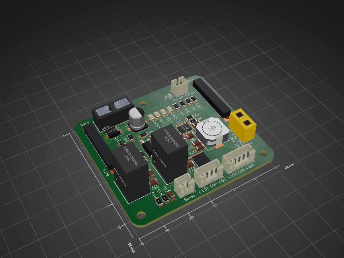
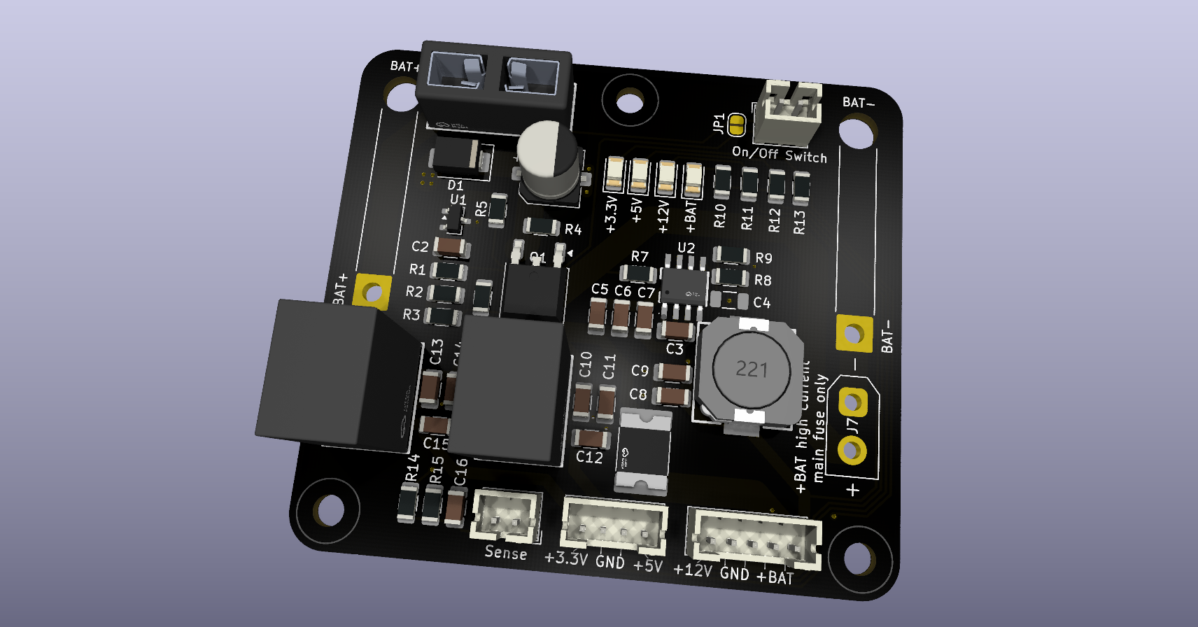
A reusable power board that turns a Makita 18V LXT battery into protected, switched power for your projects: the raw battery rail plus regulated 12 V, 5 V and 3.3 V, with a built-in low-voltage cutoff that protects the…
Battery power board is an open-source printed circuit board by scriptcoded, from the scriptcoded/18v-battery-power-board repository on GitHub, published under the CERN-OHL-P-2.0 licence. It is a 2-layer board of 62 × 56 mm with 57 parts on 24 nets, routed with 237 tracks and 35 vias.
It is built around the K7803-2000R3, K7805-2000R3 and RY9430DP8, with the AOD4185, SMBJ22A and SMD250L-30V among its other parts. Its parts include 16 capacitors, 15 resistors, 7 connectors, 5 diodes and 4 ICs. It belongs with the power boards of this library.
A reusable power board that turns a Makita 18V LXT battery into protected, switched power for your projects: the raw battery rail plus regulated 12 V, 5 V and 3.3 V, with a built-in low-voltage cutoff that protects the battery.
Designed in KiCad 10. Two layers, 56 × 62 mm, M3 mounting holes.
Not affiliated with or endorsed by Makita. "Makita" and "LXT" are trademarks of their respective owner.
Features
Battery protection: a cutoff switches everything off at about 16.3 V and back on at about 17.5 V, so a 5S Li-ion pack is never over-discharged. The battery's own signal pin is not needed.
Main fuse: replaceable 7.5 A mini blade fuse, plus a TVS diode clamping input spikes.
On/off switch input: a 2-pin header for an external switch. A solder jumper (JP1) turns the board permanently on when no switch is fitted.
Four outputs:
Rail
Source
Rating
VBAT
Switched battery, own 2.5 A polyfuse
15.8–21 V, ~2 A
12 V
RY9430 synchronous buck
2 A
5 V
K7805-2000R3 module
2 A
3.3 V
K7803-2000R3 module
2 A
High-current output: an XT30 connector on the switched battery rail for loads above 2 A. Protected by the main fuse only (7.5 A).
Battery sense output: a filtered divider giving about 3.0 V at 21 V, safe for any MCU's ADC.
Status LEDs: one per rail (VBAT, 12 V, 5 V, 3.3 V).
Power path
text
Battery ─ J1/J2 ─ F1 (7.5 A) ─┬─ TVS + bulk cap
                              └─ Cutoff (ATL431 + P-MOSFET) ─ VBAT_SW ─┬─ F2 (2.5 A) ─ VBAT out (J5)
                                                                       ├─ 12 V buck ──── J5
                                                                       ├─ 5 V module ─── J6
                                                                       ├─ 3.3 V module ─ J6
                                                                       ├─ XT30 (J7)
                                                                       └─ Sense divider ─ J4
The cutoff and the switch both act on the same MOSFET, so turning the board off (or a low battery) disconnects every output.
Connectors
All signal and power connectors are JST PH 2.0. Pin 1 is + everywhere.
J5 — HV (5-pin PH)
Pin
Signal
1
VBAT_OUT
2
VBAT_OUT
3
GND
4
GND
5
+12V
J6 — LV (4-pin PH)
Pin
Signal
1
+5V
2
GND
3
GND
4
+3V3
J4 — Battery sense (2-pin PH): pin 1 VBAT_SENSE, pin 2 GND.
Battery voltage = ADC reading × 6.92.
J3 — On/off switch (2-pin PH): closing the switch turns the board on. It carries only microamps, so any small switch works. Bridge JP1 instead if you don't use a switch.
J7 — XT30 (female): switched battery voltage, fused by F1 only. Polarity is marked on the silkscreen.
J1 / J2 — Battery wire pads: BAT+ and BAT− with strain-relief holes, for 1.5 mm² wire.
Power and ground pins are doubled on J5 and J6 to share the current, since PH contacts are rated about 2 A each. The two connectors have different pin counts, so the HV and LV cables can't be swapped.
Harness convention
Each project uses a fan-out cable from J5/J6 to small device connectors:
3-pin PH (+, NC, −): VBAT or 12 V
2-pin PH (+, −): 5 V or 3.3 V
Use "same-direction" PH cables only (pin 1 to pin 1).
Building one
Ordering
PCB: Gerbers and drill files are in exports/. 2 layers, 1.6 mm, 1 oz copper, tented vias.
Parts: see the BOM. LCSC part numbers are in the KiCad symbols' "LCSC Part" field. The 7.5 A blade fuse is not in the KiCad BOM; order it separately.
Assembly
Everything is hand-solderable with an iron and a hot-air station.
U2 (RY9430) first: its exposed pad must be soldered. Tin it thinly, then reflow the chip with hot air.
Remaining SMD parts: the electrolytic and the LEDs are best done with the iron.
Through-hole parts last: fuse holder, connectors, XT30, then the K78 modules.
Clean the flux with isopropyl alcohol, especially around U1 and R1–R3. Residue on that high-impedance node can shift the cutoff voltage.
First power-up
With no fuse and no battery, check with a multimeter for shorts between GND and each rail.
Insert the fuse, connect the battery, and measure every output before connecting any load.
Notes and safety
J1 and J2 sit before the fuse. Route and secure the battery wires so they can't chafe.
The XT30 output is protected only by the 7.5 A main fuse. Size your wiring accordingly.
Pulsed loads (e.g. stepper or motor drivers) should have their own bulk capacitor at the driver.
The board draws a small standby current even when switched off. Disconnect it from the battery for long-term storage.
Repository layout
text
*.kicad_pro / *.kicad_sch / *.kicad_pcb   KiCad project
libraries/                                Project-local symbols, footprints and 3D models
exports/                                  Gerbers, drill files and BOM per revision
License
This hardware design is licensed under the CERN Open Hardware Licence Version 2 – Permissive (CERN-OHL-P-2.0). See LICENSE.
It measures 62 × 56 mm and has 2 copper layers, 1.6 mm thick.
What parts does the Battery power board use?
57 parts, built around the K7803-2000R3, K7805-2000R3, RY9430DP8 and AOD4185. The full list of its parts is on this page, with links to each part's symbol and footprint where PCBKit's library has them.
Where can I download the Battery power board KiCad files?
From the scriptcoded/18v-battery-power-board repository on GitHub, at the commit this page was made from: the board is battery_power_board.kicad_pcb and its schematic battery_power_board.kicad_sch. PCBKit opens the board in the browser, with nothing to install.
Can I use the Battery power board design in my own project?
Its repository publishes it under the CERN-OHL-P-2.0 licence: you may reuse it on that licence's terms (keep the author's notice, and for a copyleft licence share your changes alike).
A compact interface for three NPN, PNP or logic sensors on an FRC robot. Each port has a removable 5 V / 12 V power jumper; input type is configured in software.