2 layers40 × 20 mm
 scrapcomputing/WavetablePi69
A wavetable module powered by a Raspberry Pi Zero 2W and mt32-pi
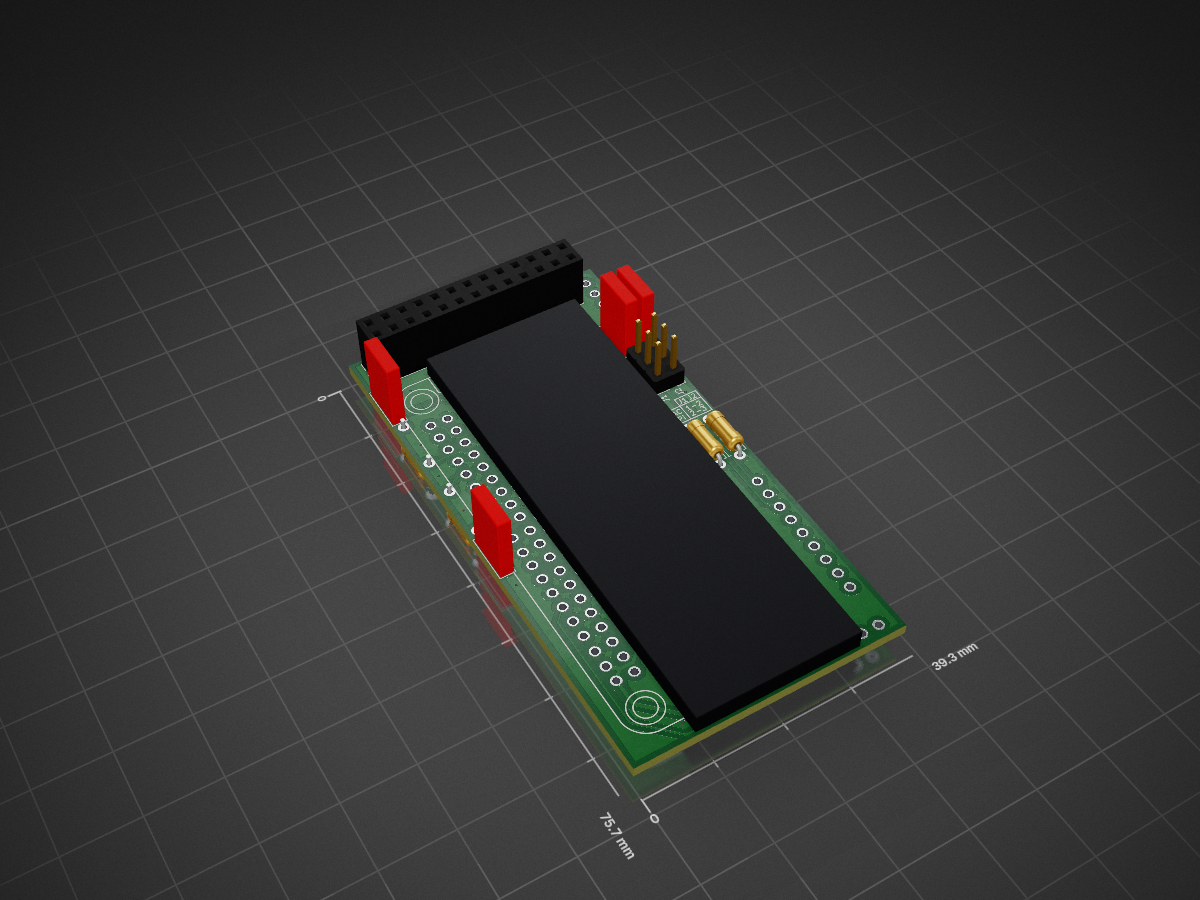
WavetablePi is an open-source printed circuit board by scrapcomputing, from the scrapcomputing/WavetablePi repository on GitHub, published under the GPL-2.0 licence. It is a 2-layer board of 39.3 × 75.7 mm with 13 parts on 23 nets, routed with 169 tracks and 20 vias.
Its parts include 2 capacitors and 2 resistors. It belongs with the audio and music boards and the Raspberry Pi (Linux) boards of this library.
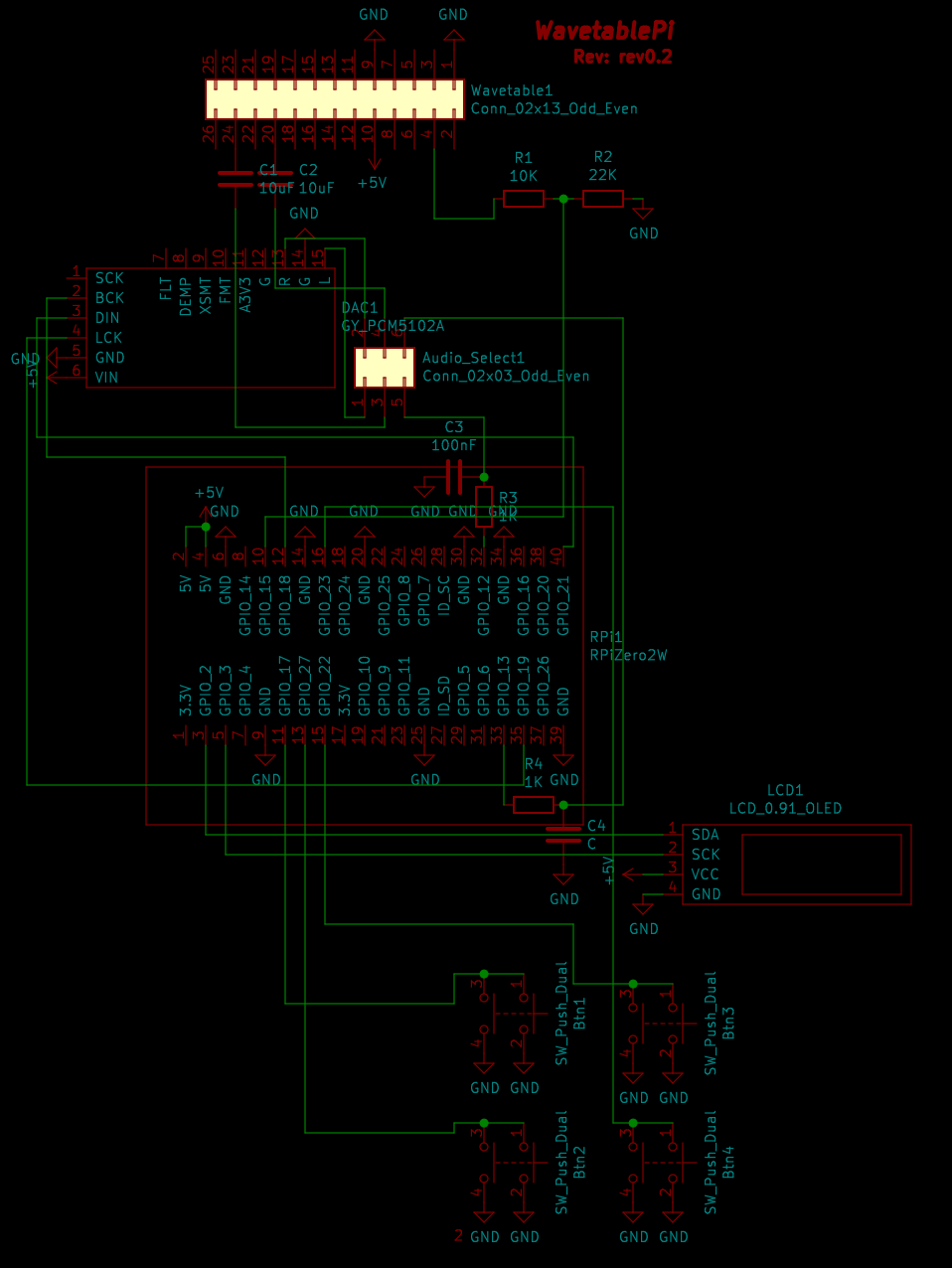
WavetablePi is a wavetable module based on the Raspberry Pi Zero 2 W running mt32-pi. It is capable of emulating several midi synthesizers, including mt32, sc55 and general midi with custom sound fonts. For a complete feature list please refer to the mt32-pi project.
For controlling the mt32-pi from DOS, please use mt32-pi-control.
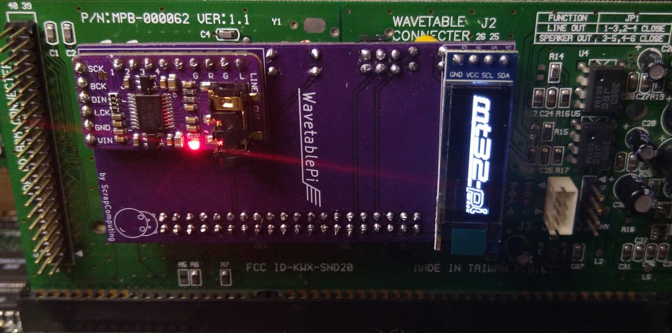
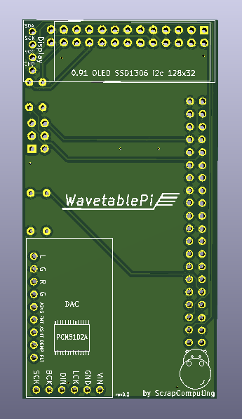
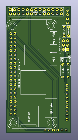
mt32-pi.cfg. You may need to set gpio_baud_rate = 31250.These tips are based on feedback from ThatRed (many thanks!). Feel free to check out the full text: https://github.com/scrapcomputing/WavetablePi/issues/1
| Item | # | Description |
|---|---|---|
| Raspberry Pi Zero 2 W | 1 | The older RPi Zero is not fast enough |
| 40-pin 2x20 male header 2.54mm pitch | 1 | For attaching the RPi to the board. |
| 26-pin 2x13 female header 2.54mm pitch | 1 | For attaching the board to the wavetable header |
| 6-pin 2x3 pin male header 2.54mm pitch | 1 | For the audio select jumpers |
| Jumper 2.54mm pitch | 2 | Jumpers for the audio selection header |
| Capacitor 10uF through-hole ceramic | 2 | |
| Capacitor 100nF through-hole ceramic | 2 | C3 and C4 which form the PWM audio low-pass filter along with R3 and R4. 100nF is for a 1.6KHz cutoff frequency. Use lower values for higher cutoff |
| Resistor 22K Ohm | 1 | |
| Resistor 10K Ohm | 1 | |
| Resistor 1K Ohm | 2 | R3 and R4, which along with C3 and C4 form a low-pass filter of the PWM audio |
| 0.91 OLED SSD1306 I2C 128x32 module | 1 | (Optional) |
| PCM5102A I2S DAC Module (aka GY PCM5120) | 1 | (Optional but highly recommended) Please check the PCB for the supported dimensions and form factor! |
| Qty | Value | Footprint | References |
|---|---|---|---|
| 2 | 10uF | Capacitor_THT:C_Rect_L7.0mm_W2.0mm_P5.00mm | 10uF, 10uF |
| 2 | 1K | Resistor_THT:R_Axial_DIN0207_L6.3mm_D2.5mm_P7.62mm_Horizontal | R3, R4 |
| 1 | 100nF | Capacitor_THT:C_Rect_L7.0mm_W2.0mm_P5.00mm | C3 |
| 1 | 10K | Resistor_THT:R_Axial_DIN0207_L6.3mm_D2.5mm_P7.62mm_Horizontal | 10K |
| 1 | 22K | Resistor_THT:R_Axial_DIN0207_L6.3mm_D2.5mm_P7.62mm_Horizontal | 22K |
| 1 | C | Capacitor_THT:C_Rect_L7.0mm_W2.0mm_P5.00mm | C4 |
| 1 | Conn_02x03_Odd_Even | Connector_PinHeader_2.54mm:PinHeader_2x03_P2.54mm_Vertical | Audio Select |
| 1 | Conn_02x13_Odd_Even | Connector_PinSocket_2.54mm:PinSocket_2x13_P2.54mm_Vertical | Wavetable1 |
| 1 | GY_PCM5102A | Custom:GY_PCM5102A | DAC1 |
| 1 | LCD_0.91_OLED | Custom:LCD_0.91_OLED | LCD1 |
| 1 | RPiZero2W | Custom:RPiZero2W | Raspberry Pi Zero 2 W |
It measures 39.3 × 75.7 mm and has 2 copper layers, 1.6 mm thick.
13 parts. The full list of its parts is on this page, with links to each part's symbol and footprint where PCBKit's library has them.
From the scrapcomputing/WavetablePi repository on GitHub, at the commit this page was made from: the board is kicad/WavetablePi.kicad_pcb. PCBKit opens the board in the browser, with nothing to install.
Its repository publishes it under the GPL-2.0 licence: you may reuse it on that licence's terms (keep the author's notice, and for a copyleft licence share your changes alike).


samyk/magspoof
A portable device that can spoof/emulate any magnetic stripe, credit card or hotel card "wirelessly", even on standard magstripe (non-NFC/RFID) readers.

fossasia/pslab-scripts
Pocket Science Lab - Scripts for Sensor Experiments


willem-pennings/balancing-cube
A cube that balances itself in a corner or edge using reaction wheels

VoronDesign/Voron-Hardware
Cool Hardware designed by the Voron Design group

hoglet67/RGBtoHDMI
Bare-metal Raspberry Pi project that provides pixel-perfect sampling of Retro Computer RGB/YUV video and conversion to HDMI