
2 layers50 × 35 mm

Reverse-engineered LOGICDATA COMPACT-e-3-VAL (ErgoSwiss hydraulic desk) handset bus: height readback + ESP32/ESPHome control through a $3 optocoupler tap. First public decode of the COMPACT-e-3's 9-bit serial protocol.
Desk is an open-source printed circuit board by scottdube, from the scottdube/deskhack repository on GitHub, published under the MIT licence. It is a 2-layer board of 94 × 60 mm with 17 parts on 38 nets, routed with 103 tracks and 0 vias.
Its parts include 7 resistors, 4 connectors and 2 ICs. It belongs with the home automation and IoT boards and the ESP32 boards of this library.
Home Assistant control and height readback for an ErgoSwiss hydraulic standing desk running a LOGICDATA COMPACT-e-3-VAL-ES-US control box ("Compact-3-eco", software V290) — without buying the vendor Memory handset, and without opening either sealed box.
The desk shipped with a dumb up/down panel: no presets, no display. This project taps the 7-pin DIN handset cable inline, drives the button lines from an ESP32 through optocouplers, and reads the desk's height from a previously undocumented serial broadcast the control box sends on one of the handset pins. The original panel keeps working in parallel.
As far as I can tell this is the first public decode of the COMPACT-e-3 handset bus. The well-known reverse-engineering projects (RoboDesk, logicdata-standing-desk) target the COMPACT-e-2L, whose framing differs in an important way (see below).
Everything below was measured on real hardware with a $12 FX2LP logic analyzer
and sigrok-cli; nothing is copied from other models' documentation.
7-pin DIN (DIN 45329 family) between handset and control box. Wire colours in the cheap extension cable used for the tap:
| wire | function |
|---|---|
| brown | GND |
| red | +5V supply to handset |
| white | HS line — assert high to drive UP |
| yellow | HS line — assert high to drive DOWN |
| green | HS line, unused by the basic panel (memory functions) |
| blue | HS line, unused by the basic panel (memory functions) |
| black | serial data out of the box, idles high |
Button lines are active-high and high-impedance: the box's inputs are sensitive enough that a multimeter in ohms mode will command motion (ask me how I know). A dumb panel is nothing but switches connecting HS lines to the +5V rail.
The data line is 1000 baud, 9 data bits, no parity, 1 stop, LSB-first — a
classic 9-bit multi-drop bus. Community docs for the COMPACT-e-2L describe
"1000 baud with even parity"; on this box that is a misread of the 9th data
bit. The framing here was solved by constraint propagation over the raw bit
runs (every 0 must sit inside a frame; see dataline.py and messages.py),
not assumed.
Packets are two 9-bit words, sent only when the displayed height changes
(one packet per inch of travel) plus a fixed handshake burst at the start of
any button press. Packet: 0x07F header, then the payload word.
height_inches = (245 - (payload & 0xFF)) / 2Verified against a tape measure at four points across the full travel (69–96 cm on this desk, 27.0–38.0 in): every reading within 0.5 cm. The box counts pump-motor Hall pulses internally, so this is the same position the controller itself acts on.
You do not need 9-bit UART support to read this bus — a plain 8N1 UART at 1000 baud recovers every payload byte intact. But how the packet arrives depends on how the UART handles framing errors, and real ESP32 silicon differs from the obvious simulation:
0xFE
sync marker followed by the height byte.00 7F <payload>: the header comes through
verbatim as 0x7F, each framing error also emits a 0x00 artifact, and
the payload byte is unmangled.Either way the sync-then-payload structure survives. On the ESP32: skip
0x00, treat 0x7F as "next byte is payload".
Filtering the handshake burst is easy thanks to an accident of the encoding:
real heights are always odd bytes (245 - 2*inches), and the handshake
constants are even or outside the travel range — except 0x0BF, which
aliases a true 27.0 in reading. Its tell is timing: as a handshake word it
arrives within ~400 ms of the others, as a real height it arrives alone, so
reject 0xBF seen within 600 ms of other handshake traffic. The working
lambda is in desk.yaml.
Eight components, all through-hole:
The tap itself is a male-female 7-pin DIN extension cable cut in half and landed on lever nuts, so the whole thing unplugs back to stock in seconds.
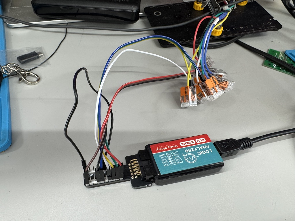
Nothing is soldered and nothing on the desk is modified — the box and the original panel each keep their own connector, and the lever nuts sit in between. Pull the two halves and the desk is stock again.
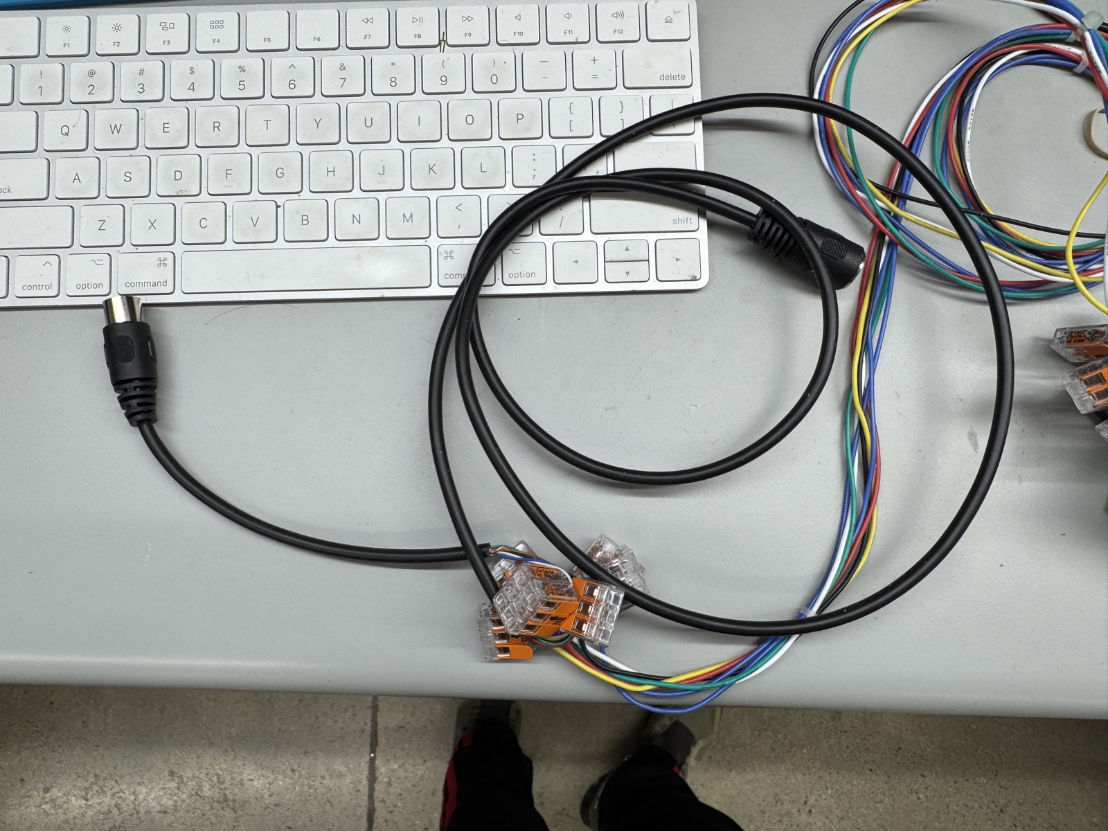
This rig is the whole trick, and it generalises. It is a $10 extension cable, not the desk's harness. Cutting it gives you seven conductors broken out into lever nuts, which is simultaneously a probe point for the logic analyzer and an injection point for the ESP32 — read the bus and drive it without ever putting a knife near the cable that came with the machine. Get it wrong, unplug two connectors, and the desk has never been touched. Any bus that runs through a detachable cable can be attacked this way.
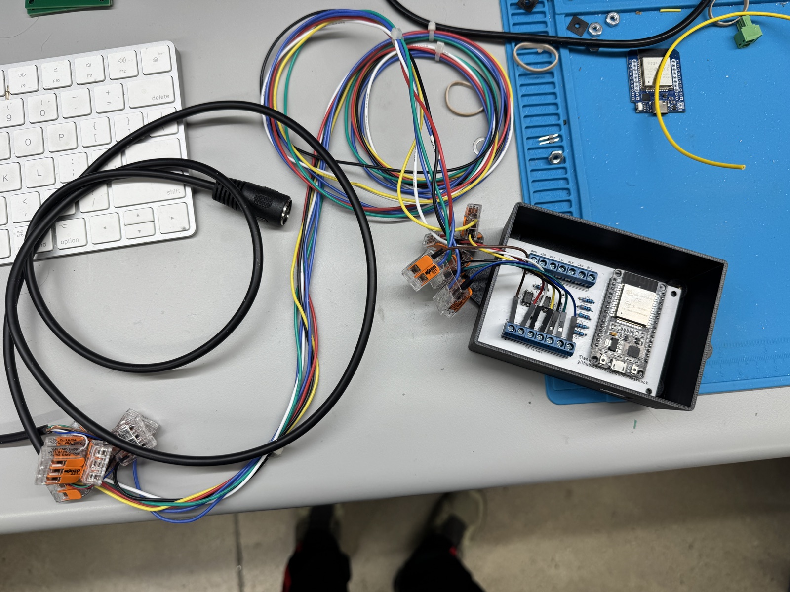
The board keeps the same idea: J1 and J4 are wired straight through, so the control box and the original handset each land on their own terminal block and the ESP32 sits across the pair. The panel goes on working exactly as before.
The handset cable is seven conductors plus a shield, and the shield is not grounded here. That is deliberate, and it is worth stating plainly because the instinct on seeing an ungrounded shield is that somebody forgot.
It is not grounded in the desk's own wiring. The two halves of the tap have their drains joined to each other, so the shield stays electrically continuous end to end exactly as it was before the cable was cut — and it terminates nowhere, exactly as it did before.
Why not "improve" it: the whole design goal is that the control box cannot tell the difference. Everything else here is built that way — the original panel keeps working, the box keeps its own connector, nothing is soldered to the desk. Bonding the shield to logic ground would be a change to a mains-fed system whose internal grounding we cannot see, in exchange for a benefit nothing has demonstrated a need for. If the box grounds the shield at its end, adding a second bond creates a loop.
No idea why LOGICDATA left it floating. Matching what the manufacturer did is the conservative choice when you do not know the reason.
kicad/ contains a KiCad 10 project (ERC-clean, footprints assigned) with the
interface circuit and a 30-pin ESP32 DevKit V1 socket, ready for board layout.
The schematic is generated — edit kicad/gen_sch.py and rerun rather than
editing the sheet, or retire the generator once you start hand-routing.
desk.yaml is a complete ESPHome configuration:
The cover face is not a convenience — on Home Assistant it is the only part of this firmware a voice assistant can reach without extra configuration, and that is worth stating plainly because the sit/stand buttons look like the obvious target.
HA's local sentence matcher only recognises entities in a fixed set of domains.
Measured against home-assistant-intents (en, 851 sentence templates): every
template with a {name} slot carries a requires_context.domain allow-list, and
the union of every domain any template can target is
binary_sensor climate cover fan input_boolean lawn_mower light lock
media_player person scene script sensor switch todo vacuum valve weather
button is not in that set. So button.<device>_sit / _stand cannot be
matched by any phrasing — and entity aliases do not help, because an alias
only supplies candidate text for a {name} slot and there is no {name}
template that accepts a button.
What this costs depends on your pipeline. With a purely local assistant, the
buttons are simply unreachable by voice. With an LLM conversation agent and
"prefer handling commands locally" enabled, they still work — but they miss the
local matcher every time and fall through to the LLM, so every "sit"/"stand"
pays a full cloud round trip while cover commands answer instantly. That
asymmetry is easy to misread as a problem with the desk, the ESP32 or the WiFi;
it is none of those.
Two ways to get fast sit/stand:
intent_script that
presses the buttons. This keeps one definition of "sit" and "stand" — in this
firmware, next to the duty-cycle watchdog — and preserves a non-travel-end
sitting height.Copy wifi.yaml.example to wifi.yaml first.
Everything runs on a capture exported to CSV
(sigrok-cli -i cap.sr -O csv > cap.csv):
| tool | what it does |
|---|---|
probe.py | per-channel characterization: idle level, edges, implied baud from narrowest pulse |
timeline.py | button lines as a deglitched state timeline |
dataline.py | bit-time histogram and exhaustive UART framing search |
messages.py | packet segmentation + solved 9N1 decode — the useful one |
viewer.py | renders a capture as a self-contained interactive HTML waveform viewer |
make_test_capture.py | synthetic capture for self-testing the toolchain |
Verified on: ErgoSwiss "Steuerung Compact-3-eco 110V V290" (P/N 124.30290),
LOGICDATA type COMPACT-e-3-VAL-ES-US, revision 3/1.9.14, US 120 V. The VAL
firmware is hydraulic-specific ("only for hydraulic lift system — modified
parameters"). Other COMPACT-e-3 variants likely match; measure before you
trust — probe.py will tell you in one capture.
MIT. If this saved you a €63 handset or an afternoon with a logic analyzer, pay it forward.
| Qty | Value | Footprint | References |
|---|---|---|---|
| 3 | 22k | Resistor_THT:R_Axial_DIN0207_L6.3mm_D2.5mm_P7.62mm_Horizontal | R5, R6, R7 |
| 2 | 100k | Resistor_THT:R_Axial_DIN0207_L6.3mm_D2.5mm_P7.62mm_Horizontal | R3, R4 |
| 2 | 330 | Resistor_THT:R_Axial_DIN0207_L6.3mm_D2.5mm_P7.62mm_Horizontal | R1, R2 |
| 2 | DIN harness | TerminalBlock_Phoenix:TerminalBlock_Phoenix_MKDS-1,5-7_1x07_P5.00mm_Horizontal | J1, J4 |
| 2 | ESP32 DevKit V1 | Connector_PinSocket_2.54mm:PinSocket_1x15_P2.54mm_Vertical | J2, J3 |
| 2 | PC817 | Package_DIP:DIP-4_W7.62mm | U1, U2 |
| 1 | TestPoint_Square | TestPoint:TestPoint_Pad_2.0x2.0mm | TP1 |
The 14 most common of 17 parts.
It measures 94 × 60 mm and has 2 copper layers, 1.6 mm thick.
17 parts. The full list of its parts is on this page, with links to each part's symbol and footprint where PCBKit's library has them.
From the scottdube/deskhack repository on GitHub, at the commit this page was made from: the board is kicad/desk.kicad_pcb and its schematic kicad/desk.kicad_sch. PCBKit opens the board in the browser, with nothing to install.
Its repository publishes it under the MIT licence: you may reuse it on that licence's terms (keep the author's notice, and for a copyleft licence share your changes alike).


hoglet67/RGBtoHDMI
Bare-metal Raspberry Pi project that provides pixel-perfect sampling of Retro Computer RGB/YUV video and conversion to HDMI


hackclub/OnBoard
💡 Join 1,000 teenagers and make your first PCB with a $100 grant!

DDeGonge/OS-ARM
This arm is not industrial and it will not be fast, but that is not my goal. But it will hopefully be a very nice looking arm fully capable of 6dof motion, cheap enough to keep it accessable but capable enough to…

