2 layers103 × 30.5 mm

 schlae/amiga-hddlw77
Adapts a regular PC floppy drive for high density operation on an Amiga computer
Amiga hddlw is an open-source printed circuit board by schlae, from the schlae/amiga-hddlw repository on GitHub. It is a 2-layer board of 93.5 × 20.3 mm with 9 parts on 38 nets, routed with 170 tracks and 3 vias.
Its parts include 6 connectors, 1 capacitor and 1 IC. It belongs with the retro computing and games boards and the FPGA and CPLD boards of this library.
Late-model Amiga computers use customized floppy drives (like the Chinon FZ-357A) to be able to read and write high-density floppy disks (colloquially known as 1.44MB floppies, although the Amiga can store 1.76MB because it packs in four additional sectors per track.)
Why a customized floppy drive? The Amiga custom chip, Paula, only supports the slower bit rate used by double-density floppy disks. Instead of spending a bunch of money to change the Paula chip, Commodore engineers got a customized floppy drive that spun the disk at half speed when it detected a high-density floppy disk.
In the 1990s, some 3rd party vendors released Amiga compatible floppy drives. One such design is the AMTRADE "The Real HD-Drive" A357. It uses a modified Sony MPF920-E or a TEAC FD-235HF (both fairly common) along with a small adapter circuit board containing a 16V8 PAL.
I've done a bit of reverse engineering to understand how the A357 works, and I've been able to build a functional replica. It's not an exact copy because the original PAL is locked. I'm calling it the Herr Doktor Diskettenlaufwerk, or HDDLW.
Please note that I have not fabbed out this design yet, and although the design is tested and expected to work, go forward at your own risk.
The board is a simple 2-layer affair with a small handful of parts. The dimensions are 93.5mm x 20.3mm (3.68" x 0.8").
Install a 20-pin DIP socket in position U1 just in case you have trouble programming the PAL. All parts, with the exception of J2, J5, and J6, should be installed on the top side of the board.
J4 should be a Molex 4-pin header with a key. In a pinch, you can sub it out with a standard 4-pin header but it will be very easy to connect the cable backwards, which will put 12V on the drive's 5V rail, destroying everything!
Install either J5 or J6 depending on the drive you plan to use. If you install both, J5 will interfere with the drive select jumpers on the Sony drive and potentially damage them.
Jumper J3 should be set to 1 for DF0 and 2 for DF1. Position 3 has not been tested yet but may work.
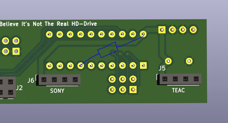
You will (most likely) need to add a bodge resistor to the design for it to operate properly on many drives. This is because the pullup on the INDEX line on the drive itself is weak or nonexistent. Connect a 10K ohm resistor from pin 7 of the PAL to pin 20 of the PAL.
(Bottom view of the board)
See the source file.
The logic equations are assembled using galette and can be burned to the PAL using a number of different tools. I use the TL-866 with the minipro tool under Linux, along with the ATF16V8B. The speed grade is not critical.
The HDDLW has been tested with the two floppy drives below. It may be possible to use it with other drives, but you will need to investigate to figure out the clock connection that sets the motor RPM. You will also need to figure out how to get the high density select signal onto pin 4 of the drive.
Perform the following changes

Perform the following changes

TEAC used several different board versions, so your board may not look exactly alike. The example below uses R12 instead of R9, and S5 has been moved although it retains the same designator.

Another alternative board uses R12 (as above) but uses S6 instead of S5.

The drive modifications intercept the clock signal that goes between the floppy drive's main control IC and the motor controller, bringing them out to two unused pins on the floppy connector. They also enable the undocumented feature that provides a high-density detect output on pin 4.
The PAL checks for high density disks by looking at pin 4. If a high density disk is inserted, the PAL
10101010... to the Amiga to let it know that
this is a high-density drive/disk.If a double-density disk is inserted, the PAL
11111111..., a double-density drive/diskAnd that's about it.
Some folks have issues where high density disks will sometimes read but will not format correctly. This can be caused by the motor speed not regulating well at the lower RPM. On the Sony drive, you can replace R21 with a 68K resistor. The TEAC drives may have similar problems but I haven't figured out a rework for them.
This work is licensed under a Creative Commons Attribution-ShareAlike 4.0 International License. See https://creativecommons.org/licenses/by-sa/4.0/.
| Qty | Value | Footprint | References |
|---|---|---|---|
| 2 | Power Out | Connector_PinSocket_2.54mm:PinSocket_1x04_P2.54mm_Vertical | J5, J6 |
| 1 | 0.01uF | Passive:CAPAC200 | C1 |
| 1 | Amiga Side | Conn:HEADER_2x17_254_SHROUDED | J1 |
| 1 | Floppy Drive | Connector_PinSocket_2.54mm:PinSocket_2x17_P2.54mm_Vertical | J2 |
| 1 | GAL16V8 | Active:DIP254P762X635-20 | U1 |
| 1 | LOGO | LOGO | G*** |
| 1 | Power In | Connector_PinHeader_2.54mm:PinHeader_1x04_P2.54mm_Vertical | J4 |
| 1 | SEL | Connector_PinHeader_2.54mm:PinHeader_2x03_P2.54mm_Vertical | J3 |


FrameworkComputer/ExpansionCards
Reference designs and documentation to create Expansion Cards for the Framework Laptop

VoronDesign/Voron-Hardware
Cool Hardware designed by the Voron Design group

hackclub/OnBoard
💡 Join 1,000 teenagers and make your first PCB with a $100 grant!


adamws/kicad-kbplacer
KiCad plugin for automatic keyboard's key placement and routing
It measures 93.5 × 20.3 mm and has 2 copper layers, 1.6 mm thick.
9 parts. The full list of its parts is on this page, with links to each part's symbol and footprint where PCBKit's library has them.
From the schlae/amiga-hddlw repository on GitHub, at the commit this page was made from: the board is amiga-hddlw.kicad_pcb and its schematic amiga-hddlw.kicad_sch. PCBKit opens the board in the browser, with nothing to install.
Its repository states no licence, so its author keeps all rights: ask schlae before reusing the design.