2 layers38.1 × 87.2 mm
AmdekDaughterBoard
schlae/AmdekDVM
Reverse engineering Amdek DVM video card for the Apple II
8 parts4CERN-OHL-P-2.0

 schlae/AmdekDVM4
Reverse engineering Amdek DVM video card for the Apple II
AmdekDVM is an open-source printed circuit board by schlae, from the schlae/AmdekDVM repository on GitHub, published under the CERN-OHL-P-2.0 licence. It is a 2-layer board of 279.9 × 76.1 mm with 69 parts on 270 nets, routed with 2,060 tracks and 155 vias.
It is built around the 74LS04PC, 74LS10PC and 74LS175PC, with the 74LS21PC, 74LS30PC and 74LS51P-E among its other parts. Its parts include 38 ICs, 23 capacitors, 3 resistors and 3 connectors. It belongs with the retro computing and games boards of this library.


The Amdek DVM allowed RGB digital monitors to be connected to Apple II computers (which normally output composite video).
This project is a reverse-engineered version of this card.
It uses readily-available TTL logic chips, with no programmable devices at all.
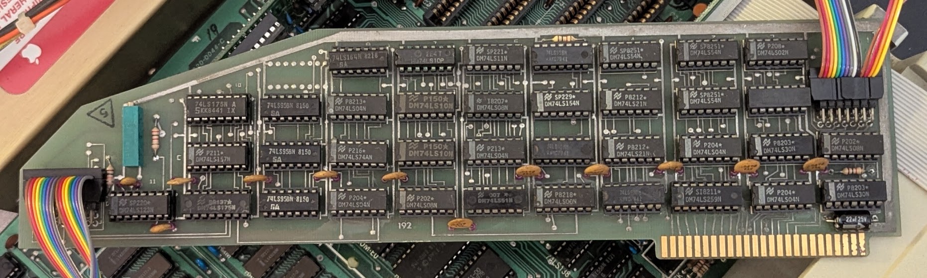
Note: The photo shows an original DVM card since I have not fabricated my design
The main board is 280mm x 76mm (11" x 3"). It is a simple 2-layer board. It has an edge connector on the bottom, and you may want to have it gold plated, but this isn't strictly necessary. No edge bevel is required but it may make it easier to insert into the connectors on the Apple II (or you could add one with a file).
The daughterboard is 38mm x 87mm (1.5" x 3.435"). It is a simple 2-layer board and could even be reduced down to a 1-layer design if you have access to such a fab process.
RV2 is actually a fixed resistor, 2K. Solder it from pin 1 to pin 3.
C3-C13 are just bypass capacitors and could easily be subbed out with 0.1uF.
C14-C23 are not stuffed on the original board, but it would be harmless to place 0.1uF capacitors here.
The daughterboard (actually two separate boards, see the photos below) should have machine-pin sockets installed. To allow them to be plugged into the Apple II motherboard, solder additional socket pins (harvested from spare sockets) to the ends of the pins protruding from the other side of the board. Alignment is critical so that the pins will plug into the sockets on the Apple II.
The daughterboard can be assembled with regular 0.1" headers and 8-pin IDC plugs, or you can use a combined part like the CA2308PA10Z. The cable is split exactly in half, with the first 8 pins going to the 4-chip daughterboard and the second 8 pins going to the 2-chip daughterboard (with wire 9 tied to pin 1 of this daughterboard).
To build this card, you will need a video output cable wired as follows. Plug it into J2 (nearest the edge connector).
| Pin | Description |
|---|---|
| 1 | Red output |
| 2 | Green output |
| 3 | Blue output |
| 4 | Horizontal sync (positive) |
| 5 | Horizontal sync (negative) |
| 6 | Vertical sync (positive) |
| 7 | Vertical sync (negative) |
| 8 | No connect |
| 9 | Ground |
| 10 | No connect |
| 11 | Apple II text - connect to Apple II header K14 pin 2 |
| 12 | Horizontal sync from 80-column card |
| 13 | Video signal from 80-column card |
| 14 | Vertical sync from 80-column card |
Pin 11 of this cable should be wired to the Apple II video header. On my Apple II+, it looks like this.
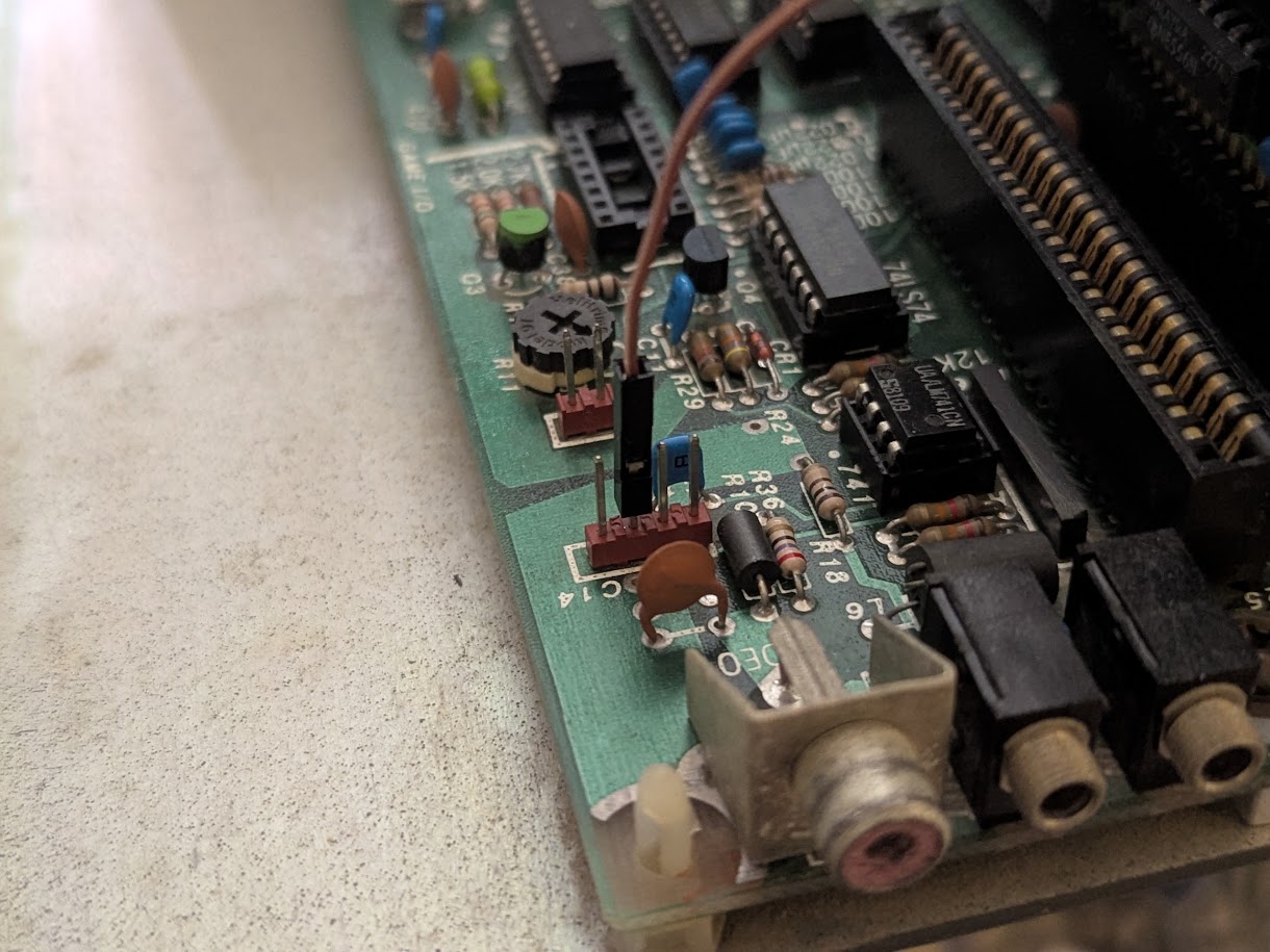
If you want to connect the DVM to a CGA-compatible monitor, wire it up as follows:
| Amdek Pin | CGA Pin | Description |
|---|---|---|
| 1 | 3 | Red output |
| 2 | 4 | Green output |
| 3 | 5 | Blue output |
| 4 | 8 | Horizontal sync (positive) |
| 6 | 9 | Vertical sync (positive) |
| 9 | 1 | Ground |
If you have an 80-column card, you can wire pins 12-14 to that card as appropriate.
You will also need a cable connected to J1 (furthest from the edge connector) wired to two daughterboards. The daughterboards act as interposers, tapping various signals on the Apple II motherboard.
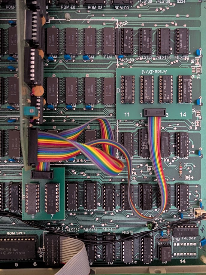
One daughterboard sits on motherboard positions D11, D12, D13, and D14, hosting the four 74LS161 chips that the Apple II uses to generate the video timing signals. It intercepts three horizontal counter bits and five vertical counter bits.
The other daughterboard sits on motherboard positions B6 and B7, hosting two 74LS257 chips. This intercepts the eight digital video bits before they go through encoding to composite video.
When you install the card, ensure you get video out of your Apple II, then adjust RV1 until you get stable pixels.
| Qty | Value | Footprint | References |
|---|---|---|---|
| 10 | 0.047 | Capacitor_THT:C_Disc_D4.3mm_W1.9mm_P5.00mm | C3, C4, C5, C6, C7, C8, C9, C10, C11, C12 |
| 10 | DNI | Capacitor_THT:C_Disc_D4.3mm_W1.9mm_P5.00mm | C14, C15, C16, C17, C18, C19, C20, C21, C22, C23 |
| 6 | 74LS95 | Package_DIP:DIP-14_W7.62mm | U6, U7, U8, U21, U23, U28 |
| 5 | 74LS04 | Package_DIP:DIP-14_W7.62mm | U10, U12, U19, U31, U36 |
| 3 | 74LS08 | Package_DIP:DIP-14_W7.62mm | U16, U18, U37 |
| 3 | 74LS10 | Package_DIP:DIP-14_W7.62mm | U13, U14, U15 |
| 3 | 74LS54N | Package_DIP:DIP-14_W7.62mm | U25, U29, U30 |
| 2 | 1K | Resistor_THT:R_Axial_DIN0309_L9.0mm_D3.2mm_P12.70mm_Horizontal | R2, R3 |
| 2 | 74LS164 | Package_DIP:DIP-14_W7.62mm | U9, U22 |
| 2 | 74LS175 | Package_DIP:DIP-16_W7.62mm | U2, U4 |
| 2 | 74LS21 | Package_DIP:DIP-14_W7.62mm | U26, U27 |
| 2 | 74LS30 | Package_DIP:DIP-14_W7.62mm | U35, U38 |
| 2 | 74LS51 | Package_DIP:DIP-14_W7.62mm | U20, U34 |
| 1 | 100 | Capacitor_THT:C_Disc_D4.3mm_W1.9mm_P5.00mm | C1 |
| 1 | 10K | Resistor_THT:R_Axial_DIN0309_L9.0mm_D3.2mm_P12.70mm_Horizontal | R1 |
| 1 | 22uF 25V | Capacitor_THT:CP_Axial_L10.0mm_D4.5mm_P15.00mm_Horizontal | C13 |
| 1 | 2K | Potentiometer_THT:Potentiometer_Bourns_3006P_Horizontal | RV2 |
| 1 | 33 | Capacitor_THT:C_Disc_D4.3mm_W1.9mm_P5.00mm | C2 |
| 1 | 5K | Potentiometer_THT:Potentiometer_Bourns_3006P_Horizontal | RV1 |
| 1 | 74LS00 | Package_DIP:DIP-14_W7.62mm | U24 |
| 1 | 74LS02 | Package_DIP:DIP-14_W7.62mm | U33 |
| 1 | 74LS11 | Package_DIP:DIP-14_W7.62mm | U17 |
| 1 | 74LS123 | Package_DIP:DIP-16_W7.62mm | U1 |
| 1 | 74LS157 | Package_DIP:DIP-16_W7.62mm | U3 |
| 1 | 74LS259 | Package_DIP:DIP-16_W7.62mm | U32 |
| 1 | 74LS74 | Package_DIP:DIP-14_W7.62mm | U11 |
| 1 | APPLE II | AmdekDVM:APPLE_II | J3 |
| 1 | SPARE | Package_DIP:DIP-16_W7.62mm | U5 |
| 1 | TO_DAUGHTERBOARD | Connector_PinHeader_2.54mm:PinHeader_2x08_P2.54mm_Horizontal | J1 |
| 1 | VIDEO | Connector_PinHeader_2.54mm:PinHeader_2x07_P2.54mm_Horizontal | J2 |
It measures 279.9 × 76.1 mm and has 2 copper layers, 1.6 mm thick.
69 parts, built around the 74LS04PC, 74LS10PC, 74LS175PC and 74LS21PC. The full list of its parts is on this page, with links to each part's symbol and footprint where PCBKit's library has them.
From the schlae/AmdekDVM repository on GitHub, at the commit this page was made from: the board is AmdekDVM.kicad_pcb and its schematic AmdekDVM.kicad_sch. PCBKit opens the board in the browser, with nothing to install.
Its repository publishes it under the CERN-OHL-P-2.0 licence: you may reuse it on that licence's terms (keep the author's notice, and for a copyleft licence share your changes alike).
schlae/AmdekDVM
Reverse engineering Amdek DVM video card for the Apple II


clemarfolly/Microdigital-TK2000
Reprodução da PCB do TK-2000 da Microdigital, clone do Micro-Professor MPF-II

ForgottenMachines/Entrex
The technologies documented here will include all like-kind systems manufactured by Nixdorf, Redifon, ROCC & Mera, all originally designed by Entrex Inc, Burlington, MA USA.


ceteras/Cobra-XP
Derived from Cobra, an experimental board for testing all kind of mods.