2 layers44.5 × 46.9 mm
OSO SWAT B1-jig
joeycastillo/Sensor-Watch
A board replacement for the classic Casio F-91W wristwatch
31 parts2.1k

 schilkp/STM32F030K6Tx_Breakout
A very simple breakout board for the STM32F030K6Tx MCU.
STM32F030K6Tx Breakout is an open-source printed circuit board by schilkp, from the schilkp/STM32F030K6Tx_Breakout repository on GitHub, published under the MIT licence. It is a 2-layer board of 35.6 × 43.2 mm with 31 parts on 43 nets, routed with 359 tracks and 34 vias.
Its parts include 8 capacitors, 5 resistors, 4 connectors, 3 diodes and 1 IC. It belongs with the interfaces and adapters boards and the STM32 boards of this library.
A very simple breakout board for the STM32F030K6Tx MCU.
Philipp Schilk 2020
https://github.com/TheSchilk/STM32F030K6Tx_Breakout

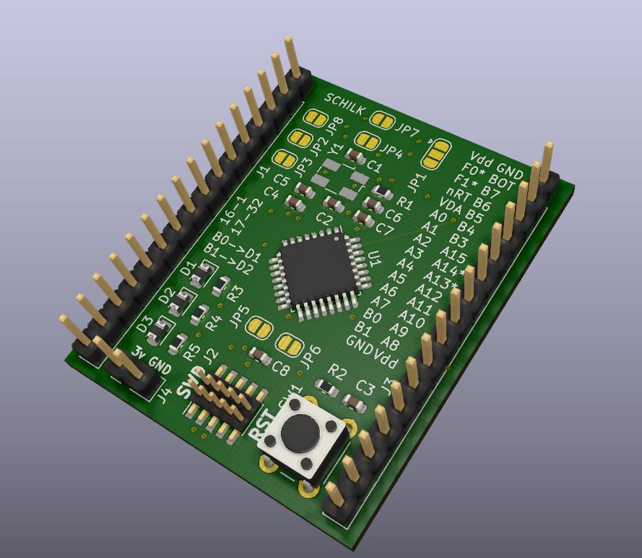
Besides SWD, 2 LEDs, space for a crystal and other supporting circuitry, there are bells and whistles.
I did however aim to expose as much functionality of the STM as possible: The crystal is optional and the IO can be exposed with two jumpers if needed. Also the VDDA Supply can be separated from VDD if a separate supply is wanted.
In fact, with the right jumper configuration this board can serve as a direct LQFP32 breakout board with all pins exposed and not set connections.
Because I hate nothing more than digging through PDFs to find out what pins the LEDs where connected to again, I included as much information as possible in the silkscreen.
ARM SWD:
Connector footprint can accept both an SMD and a TH programming header.

See TheSchilk/KiCad_Devices for footprint.
2 LEDs: Connected to pins PB0 and PB1
According to CubeMX this breakout should also be compatible with:
But that is untested. Please double check the pinout.
Here is what the Jumpers do:
JP1: Connects BOOT0 to either GND (indicated by a small arrow) or VDD, both through R1.
JP2: Connects pin F0 of the STM to the breakout header. Should only be set when not
using a crystal.
JP3: Connects pin F1 of the STM to the breakout header. Should only be set when not
using a crystal.
JP4: Connects pin 1 of MCU (VDD) to shared VDD
JP5: Connects pin 16 of MCU (GND) to shared GND
JP6: Connects pin 17 of MCU (VDD) to shared VDD
JP7: Connects pin 32 of MCU (GND) to shared GND
JP8: Connects pin 5 of MCU (VDD) to shared VDD
Which means, to use this as a STM breakout:
Set the following jumpers: JP4 JP5 JP6 JP7 JP8
If you want a straight LQFP Breakout: Set the following jumpers: JP2 JP3.
With an STM32F030K6Tx the pinout is as follows:
| Pin | Function | Pin | Function |
|---|---|---|---|
| 1 | Vdd | 32 | GND |
| 2 | F0 (1) | 31 | BOOT0 |
| 3 | F1 (1) | 30 | PB7 |
| 4 | nRST | 29 | PB6 |
| 5 | VDDA | 28 | PB5 |
| 6 | PA0 | 27 | PB4 |
| 7 | PA1 | 26 | PB3 |
| 8 | PA2 | 25 | PA15 |
| 9 | PA3 | 24 | PA14 |
| 10 | PA4 | 23 | PA13 (3) |
| 11 | PA5 | 22 | PA12 (3) |
| 12 | PA6 | 21 | PA11 |
| 13 | PA7 | 20 | PA10 |
| 14 | PB0 (2) | 19 | PA9 |
| 15 | PB1 (2) | 18 | PA8 |
| 16 | GND | 17 | GND |
(1): Crystal (2): LEDs (3); SWD
See Github releases for:
- Gerbers
- Schematic
- Interactive HTML BOM
| Qty | Value | Footprint | References |
|---|---|---|---|
| 3 | 0u1 | Capacitor_SMD:C_0603_1608Metric | C3, C6, C8 |
| 3 | 1K | Resistor_SMD:R_0603_1608Metric | R3, R4, R5 |
| 3 | PWR_1 | Jumper:SolderJumper-2_P1.3mm_Open_RoundedPad1.0x1.5mm | JP4, JP6, JP8 |
| 2 | 10K | Resistor_SMD:R_0603_1608Metric | R1, R2 |
| 2 | LED1 | Diode_SMD:D_0805_2012Metric | D1, D3 |
| 2 | c_y | Capacitor_SMD:C_0603_1608Metric | C1, C2 |
| 1 | 10n | Capacitor_SMD:C_0603_1608Metric | C4 |
| 1 | 1u | Capacitor_SMD:C_0603_1608Metric | C5 |
| 1 | 4u7 | Capacitor_SMD:C_0603_1608Metric | C7 |
| 1 | ARM_SWD | ARM_SWD_SMD_TH:ARM_SWD_SMD_TH | J2 |
| 1 | BOOT0 | Jumper:SolderJumper-3_P1.3mm_Open_RoundedPad1.0x1.5mm | JP1 |
| 1 | BREAKOUT_L | Connector_PinHeader_2.54mm:PinHeader_1x16_P2.54mm_Vertical | J1 |
| 1 | BREAKOUT_R | Connector_PinHeader_2.54mm:PinHeader_1x16_P2.54mm_Vertical | J3 |
| 1 | Crystal | Crystal:Crystal_SMD_EuroQuartz_MJ-4Pin_5.0x3.2mm | Y1 |
| 1 | GND_1 | Jumper:SolderJumper-2_P1.3mm_Open_RoundedPad1.0x1.5mm | JP5 |
| 1 | GND_2 | Jumper:SolderJumper-2_P1.3mm_Open_RoundedPad1.0x1.5mm | JP7 |
| 1 | LED2 | Diode_SMD:D_0805_2012Metric | D2 |
| 1 | PIN_2 | Jumper:SolderJumper-2_P1.3mm_Open_RoundedPad1.0x1.5mm | JP2 |
| 1 | PIN_3 | Jumper:SolderJumper-2_P1.3mm_Open_RoundedPad1.0x1.5mm | JP3 |
| 1 | PWR | Connector_PinHeader_2.54mm:PinHeader_1x02_P2.54mm_Vertical | J4 |
| 1 | RST | Button_Switch_THT:SW_PUSH_6mm | SW1 |
| 1 | STM32F030K6Tx | Package_QFP:LQFP-32_7x7mm_P0.8mm | U1 |
joeycastillo/Sensor-Watch
A board replacement for the classic Casio F-91W wristwatch

hoglet67/RGBtoHDMI
Bare-metal Raspberry Pi project that provides pixel-perfect sampling of Retro Computer RGB/YUV video and conversion to HDMI

hackclub/OnBoard
💡 Join 1,000 teenagers and make your first PCB with a $100 grant!

openwch/ch32v003
CH32V003 is an ultra-cheap RISC-V MCU with 2KB SRAM, 16KB flash, and up to 18 GPIOs that sells for under $0.10

Luos-io/luos_engine
Open-source and real-time orchestrator for cyber-physical-systems, to easily design, test and deploy embedded applications and digital twins.

BlueAndi/Pixelix
Full RGB LED matrix, based on an ESP32 and WS2812B LEDs or emulated LEDs on TFT.


It measures 35.6 × 43.2 mm and has 2 copper layers, 1.6 mm thick.
31 parts. The full list of its parts is on this page, with links to each part's symbol and footprint where PCBKit's library has them.
From the schilkp/STM32F030K6Tx_Breakout repository on GitHub, at the commit this page was made from: the board is Kicad/STM32F030K6Tx_Breakout/STM32F030K6Tx_Breakout.kicad_pcb. PCBKit opens the board in the browser, with nothing to install.
Its repository publishes it under the MIT licence: you may reuse it on that licence's terms (keep the author's notice, and for a copyleft licence share your changes alike).