
2 layers389.2 × 181.8 mm
C64
schenkmi/electronic-retro-computing-projects
In revision 2, the PCB size has been reduced by more than 50% and TAPuino support has been ditched. It now features a Micro SD slot and a few other improvements.
260 parts

In revision 2, the PCB size has been reduced by more than 50% and TAPuino support has been ditched. It now features a Micro SD slot and a few other improvements.
SD2IEC is an open-source printed circuit board by schenkmi, from the schenkmi/electronic-retro-computing-projects repository on GitHub. It is a 2-layer board of 64 × 50 mm with 52 parts on 57 nets, routed with 585 tracks and 58 vias.
It is built around the MIC5504-3.3YM5, AO3400A and LL4148. Its parts include 17 resistors, 10 capacitors, 7 connectors, 4 switches and 3 diodes. It belongs with the AVR (ATmega, ATtiny) boards of this library.


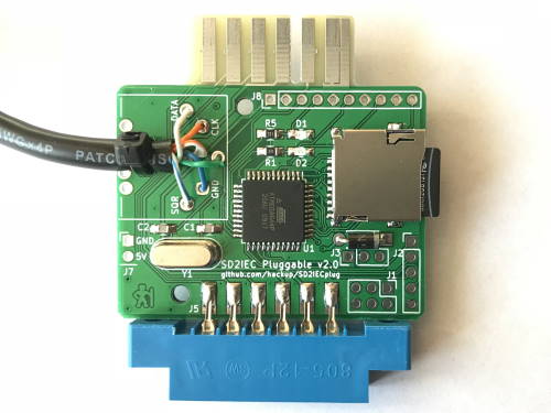
In revision 2, the PCB size has been reduced by more than 50% and TAPuino support has been ditched. It now features a Micro SD slot and a few other improvements. Note: In this revision, the numbering of the LEDs has been accidentally reversed. This has been fixed later on the master branch.
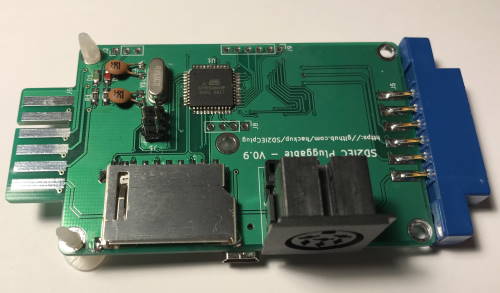
The first revision required a much larger PCB but featured a full-size SD slot and experimental support for TAPuino functionality. The latter was never tested though and probably wouldn't work.
If you don't intend to use the TAPuino functionality (and there isn't any firmware support for this yet) you can omit R16-R21 and the optocoupler U3. Also, the board can be power either through the USB or the tape port connector so you don't necessarily need to fit both.

This work is licensed under a Creative Commons Attribution-NonCommercial-ShareAlike 4.0 International License.
| Qty | Value | Footprint | References |
|---|---|---|---|
| 9 | 10K | Resistor_SMD:R_0805_2012Metric_Pad1.20x1.40mm_HandSolder | R1, R2, R3, R4, R6, R8, R10, R12, R14 |
| 5 | 100nF | Capacitor_SMD:C_0805_2012Metric_Pad1.18x1.45mm_HandSolder | C3, C4, C5, C6, C7 |
| 4 | MountingHole_Pad | MountingHole:MountingHole_2.2mm_M2_DIN965_Pad | H1, H2, H3, H4 |
| 3 | 10μF | Capacitor_Tantalum_SMD:CP_EIA-3216-10_Kemet-I_Pad1.58x1.35mm_HandSolder | C8, C9, C10 |
| 3 | 18R | Resistor_SMD:R_0805_2012Metric_Pad1.20x1.40mm_HandSolder | R5, R9, R13 |
| 3 | 22K | Resistor_SMD:R_0805_2012Metric_Pad1.20x1.40mm_HandSolder | R7, R11, R15 |
| 3 | AO3400A | Package_TO_SOT_SMD:SOT-23 | Q1, Q2, Q3 |
| 2 | 330R | Resistor_SMD:R_0805_2012Metric_Pad1.20x1.40mm_HandSolder | R16, R17 |
| 2 | 56pF | Capacitor_SMD:C_0805_2012Metric_Pad1.18x1.45mm_HandSolder | C1, C2 |
| 2 | IEC (DIN6) | DTLib:DIN6_PCB_RIGHTANGLE | J4, J5 |
| 1 | 5VDC IN | DTLib:COMMODORE_CASSETTE_EdgeMount | J2 |
| 1 | 8MHz | Crystal:Crystal_HC49-4H_Vertical | Y1 |
| 1 | ATmega1284P-20AU | Package_QFP:TQFP-44_10x10mm_P0.8mm | U1 |
| 1 | AVR-ISP-6 | Connector:Tag-Connect_TC2030-IDC-NL_2x03_P1.27mm_Vertical | J1 |
| 1 | GREEN | LED_SMD:LED_0805_2012Metric_Pad1.15x1.40mm_HandSolder | D3 |
| 1 | IEC_ALT1 | Connector_JST:JST_XH_B6B-XH-A_1x06_P2.50mm_Vertical | J8 |
| 1 | IEC_ALT2 | Connector_JST:JST_XH_B6B-XH-A_1x06_P2.50mm_Vertical | J9 |
| 1 | IEC_SEL | Button_Switch_THT:SW_DIP_SPSTx02_Slide_9.78x7.26mm_W7.62mm_P2.54mm | SW1 |
| 1 | LL4148 | Diode_SMD:D_MiniMELF | D1 |
| 1 | LOGO | DTLib:Logo | G*** |
| 1 | MIC5504-3.3YM5 | Package_TO_SOT_SMD:SOT-23-5 | U2 |
| 1 | NEXT | Button_Switch_THT:SW_Tactile_SPST_Angled_PTS645Vx58-2LFS | SW3 |
| 1 | PREV | Button_Switch_THT:SW_Tactile_SPST_Angled_PTS645Vx58-2LFS | SW2 |
| 1 | RED | LED_SMD:LED_0805_2012Metric_Pad1.15x1.40mm_HandSolder | D2 |
| 1 | RESET | Button_Switch_SMD:SW_SPST_PTS645 | SW4 |
| 1 | SD_Card | DTLib:SD_Kyocera_145638009211859+ | J3 |
schenkmi/electronic-retro-computing-projects
In revision 2, the PCB size has been reduced by more than 50% and TAPuino support has been ditched. It now features a Micro SD slot and a few other improvements.

schenkmi/electronic-retro-computing-projects
In revision 2, the PCB size has been reduced by more than 50% and TAPuino support has been ditched. It now features a Micro SD slot and a few other improvements.

schenkmi/electronic-retro-computing-projects
In revision 2, the PCB size has been reduced by more than 50% and TAPuino support has been ditched. It now features a Micro SD slot and a few other improvements.

schenkmi/electronic-retro-computing-projects
In revision 2, the PCB size has been reduced by more than 50% and TAPuino support has been ditched. It now features a Micro SD slot and a few other improvements.

schenkmi/electronic-retro-computing-projects
In revision 2, the PCB size has been reduced by more than 50% and TAPuino support has been ditched. It now features a Micro SD slot and a few other improvements.

schenkmi/electronic-retro-computing-projects
In revision 2, the PCB size has been reduced by more than 50% and TAPuino support has been ditched. It now features a Micro SD slot and a few other improvements.

schenkmi/electronic-retro-computing-projects
In revision 2, the PCB size has been reduced by more than 50% and TAPuino support has been ditched. It now features a Micro SD slot and a few other improvements.

schenkmi/electronic-retro-computing-projects
In revision 2, the PCB size has been reduced by more than 50% and TAPuino support has been ditched. It now features a Micro SD slot and a few other improvements.

schenkmi/electronic-retro-computing-projects
In revision 2, the PCB size has been reduced by more than 50% and TAPuino support has been ditched. It now features a Micro SD slot and a few other improvements.

schenkmi/electronic-retro-computing-projects
In revision 2, the PCB size has been reduced by more than 50% and TAPuino support has been ditched. It now features a Micro SD slot and a few other improvements.

schenkmi/electronic-retro-computing-projects
In revision 2, the PCB size has been reduced by more than 50% and TAPuino support has been ditched. It now features a Micro SD slot and a few other improvements.

schenkmi/electronic-retro-computing-projects
In revision 2, the PCB size has been reduced by more than 50% and TAPuino support has been ditched. It now features a Micro SD slot and a few other improvements.


formulaslug/fs-5-schematics
Electrical Design Repository for fs-5 schematics and PCBs

HexaBitsEdu/ESP32-MiniDrone
this project is a drone based on esp32 microcontroller and coreless DC motor


It measures 64 × 50 mm and has 2 copper layers, 1.6 mm thick.
52 parts, built around the MIC5504-3.3YM5, AO3400A and LL4148. The full list of its parts is on this page, with links to each part's symbol and footprint where PCBKit's library has them.
From the schenkmi/electronic-retro-computing-projects repository on GitHub, at the commit this page was made from: the board is sd2iec-kicad/SD2IEC.kicad_pcb. PCBKit opens the board in the browser, with nothing to install.
Its repository states no licence, so its author keeps all rights: ask schenkmi before reusing the design.