2 layers158 × 11 mm
Daylight Matchstick
VoronDesign/Voron-Hardware
Cool Hardware designed by the Voron Design group
22 parts1.1kGPL-3.0

 savagesmc/bandpass_filter
Kicad design of a bandpass filter circuit board.
Bandpass filter is an open-source printed circuit board by savagesmc, from the savagesmc/bandpass_filter repository on GitHub, published under the GPL-3.0 licence. It is a 2-layer board of 94 × 25.4 mm with 22 parts on 12 nets, routed with 59 tracks and 10 vias.
Its parts include 9 capacitors, 9 inductors, 2 resistors and 2 connectors.
This is an open source schemaatic and board layout for a 9th order chebyshev filter. The filter was designed on the awesome filter design tool website.
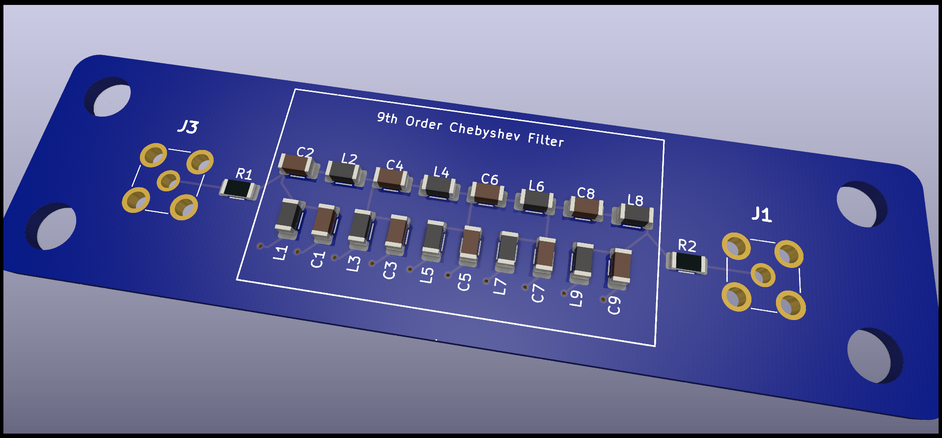
The schematic in this project is for a filter for the UHF band from 240 MHz to 1.2 GHz.
In the models folder are a number of different filters that all have the same shunt first topology, but pass different bands.
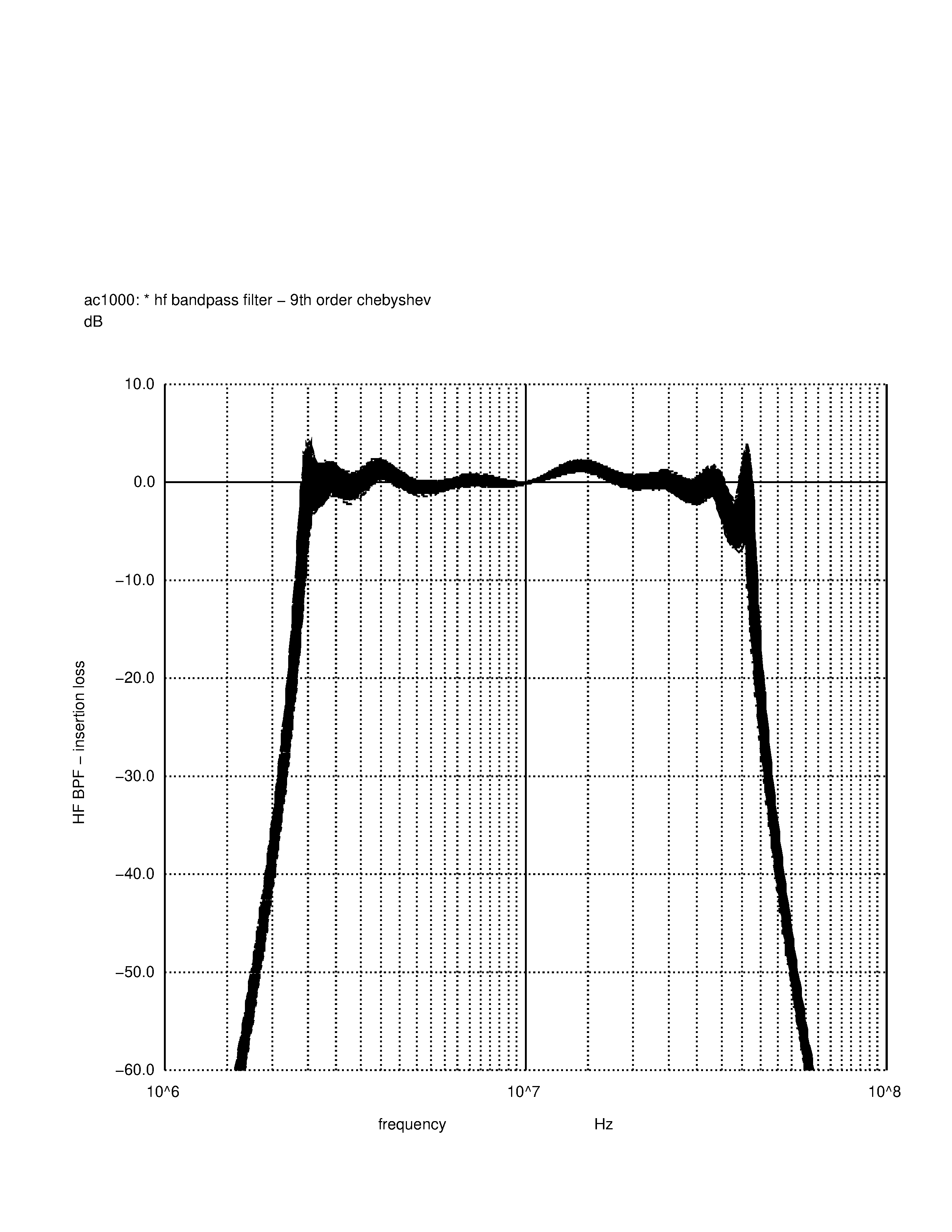
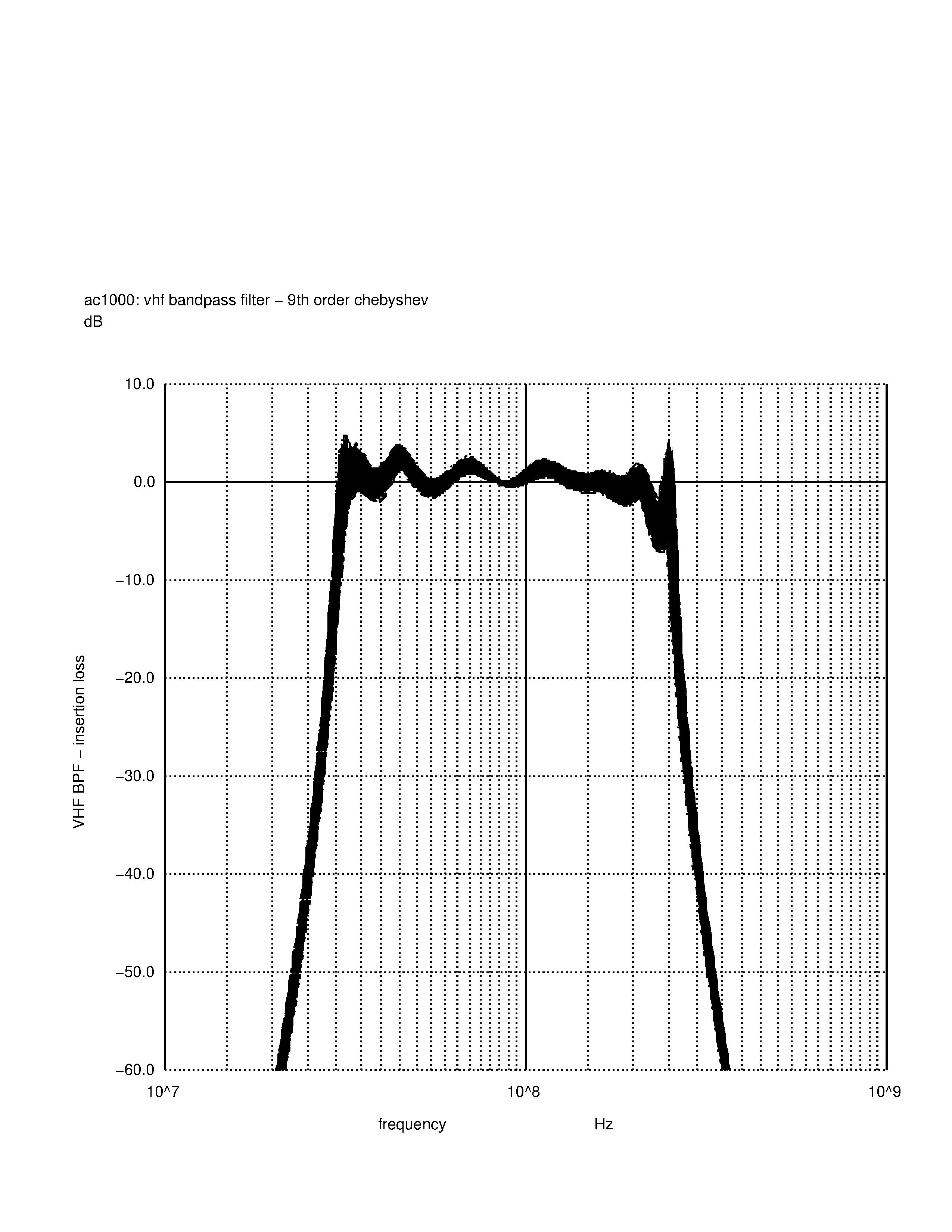
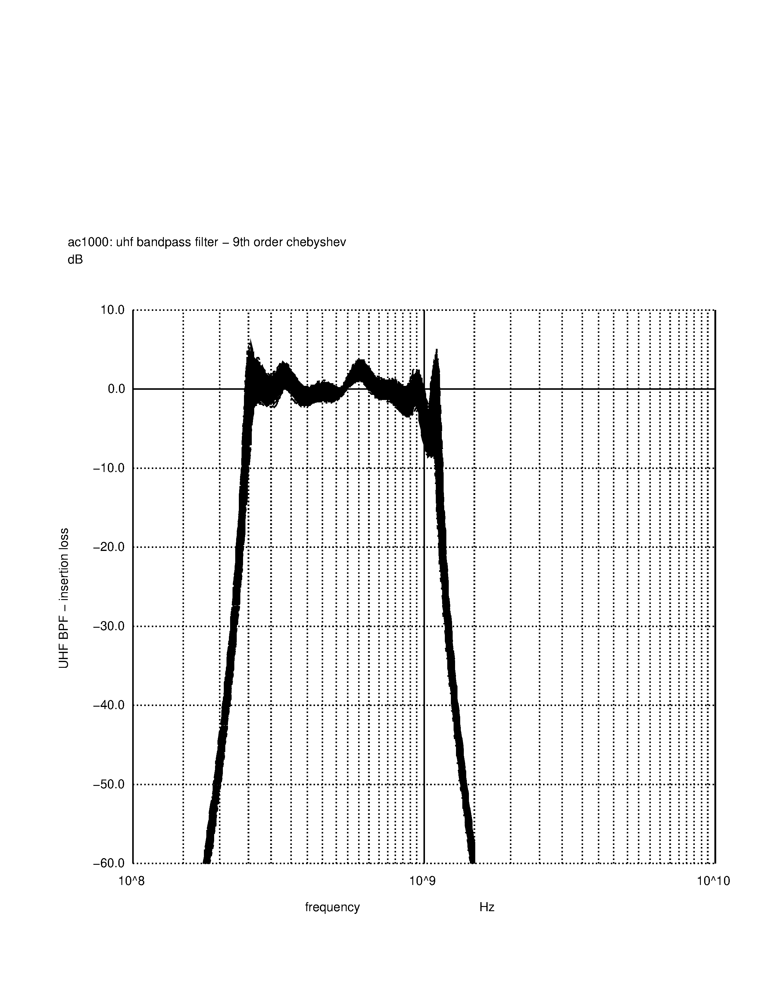
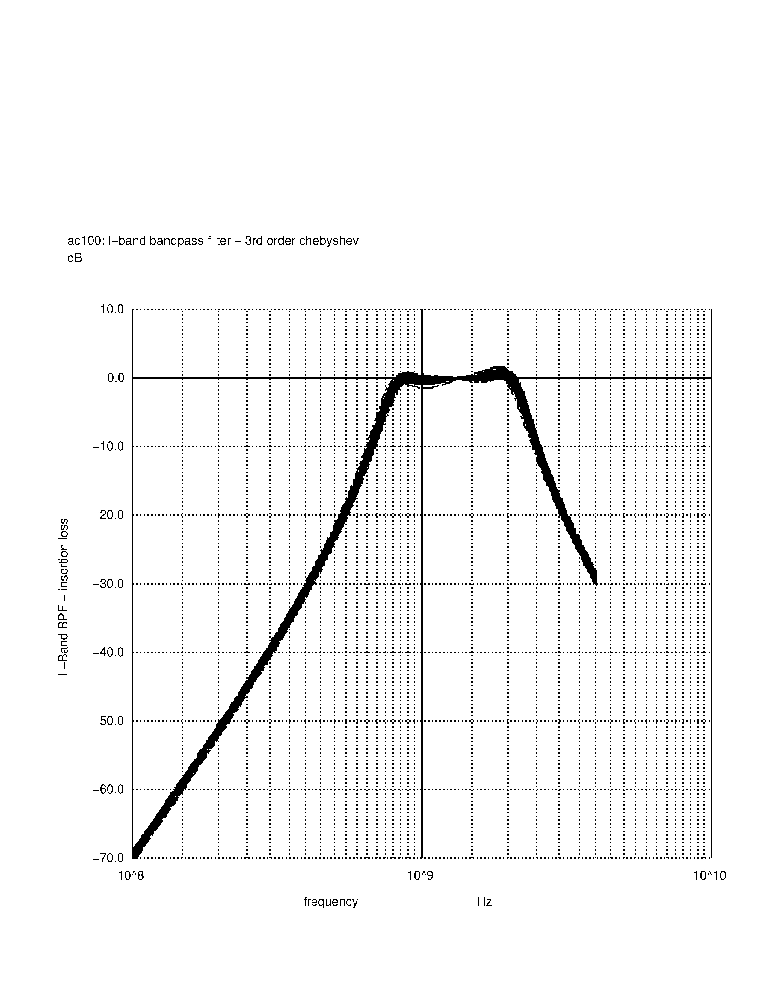
The boards that were printed can just be populated with the appropriate L's and C's to put it into the desired band. The SPICE models included in the models folder run 1000 different runs with all of the components varying within the 5% tolerance specified to form a family of curves that form an envelope of the filter response.
There is an HF bandpass filter design from 2.5 MHz to 30 MHz:
There is a VHF bandpass filter design from 30 MHz to 240 MHz:
There is the UHF bandpass filter design that is in the schematic (240 to 1100 MHz):
And there is an L-Band bandpass filter design from 1000 to 1900 MHz:
I ordered 5 of these boards from JLCPCB. It was a very simple process. I simply took the contents of the gerbers folder, zipped them up and uploaded the zipfile, and for $40 USD (including shipping), and about 2 weeks, I have a set of boards.
Once I have built one of these boards and tested it, I will post the results up here. I am interested to see how the board parasitics will affect the frequency response of these boards. I am expecting that the UHF and L-Band circuits will see some noticable deviations from the spice model filter response. However, the FR4 PCB is supposed to be good for designs all the way out to 6 GHz, so maybe there won't need to be any adjustments.
| Qty | Value | Footprint | References |
|---|---|---|---|
| 4 | 15 nH | Inductor_SMD:L_1206_3216Metric | L2, L4, L6, L8 |
| 3 | 12 nH | Inductor_SMD:L_1206_3216Metric | L3, L5, L7 |
| 3 | 8.2 pF | Capacitor_SMD:C_1206_3216Metric | C3, C5, C7 |
| 2 | 22 nH | Inductor_SMD:L_1206_3216Metric | L1, L9 |
| 2 | 4.7 pF | Capacitor_SMD:C_1206_3216Metric | C1, C9 |
| 2 | 5.6 pF | Capacitor_SMD:C_1206_3216Metric | C4, C6 |
| 2 | PCB.SMAFRA.HT | Mouser:PCBSMAFRAHT | J1, J3 |
| 2 | r=50 | Resistor_SMD:R_1206_3216Metric | R1, R2 |
| 1 | 6.8 pF | Capacitor_SMD:C_1206_3216Metric | C8 |
| 1 | 6.8 pf | Capacitor_SMD:C_1206_3216Metric | C2 |
VoronDesign/Voron-Hardware
Cool Hardware designed by the Voron Design group

hoglet67/RGBtoHDMI
Bare-metal Raspberry Pi project that provides pixel-perfect sampling of Retro Computer RGB/YUV video and conversion to HDMI

hackclub/OnBoard
💡 Join 1,000 teenagers and make your first PCB with a $100 grant!

abhishek-kakkar/BeagleLogic
A Software Suite that implements a logic analyzer with the PRU on the BeagleBone / BeagleBone Black.

Chrismettal/flipper-zero-backpacks
Backpack-style addon boards for the Flipper Zero!


CRImier/MyKiCad
My KiCad boards. Can't be bothered uploading individually anymore, so here you go.
It measures 94 × 25.4 mm and has 2 copper layers, 1.6 mm thick.
22 parts. The full list of its parts is on this page, with links to each part's symbol and footprint where PCBKit's library has them.
From the savagesmc/bandpass_filter repository on GitHub, at the commit this page was made from: the board is bandpass_filter.kicad_pcb and its schematic bandpass_filter.kicad_sch. PCBKit opens the board in the browser, with nothing to install.
Its repository publishes it under the GPL-3.0 licence: you may reuse it on that licence's terms (keep the author's notice, and for a copyleft licence share your changes alike).