
2 layers43.9 × 27.7 mm

 savagesmc/vcotestboard
test board design & layout for MAX2607 (MAX260N) part(s).
Vcotestboard is an open-source printed circuit board by savagesmc, from the savagesmc/vcotestboard repository on GitHub, published under the GPL-3.0 licence. It is a 2-layer board of 101.6 × 67.7 mm with 19 parts on 11 nets, routed with 58 tracks and 2 vias.
It is built around the MAX2607EUT+T. Its parts include 5 capacitors, 5 inductors, 4 resistors, 4 connectors and 1 crystal.
this is an open source schemaatic and board layout for the MAX2607 VCO.
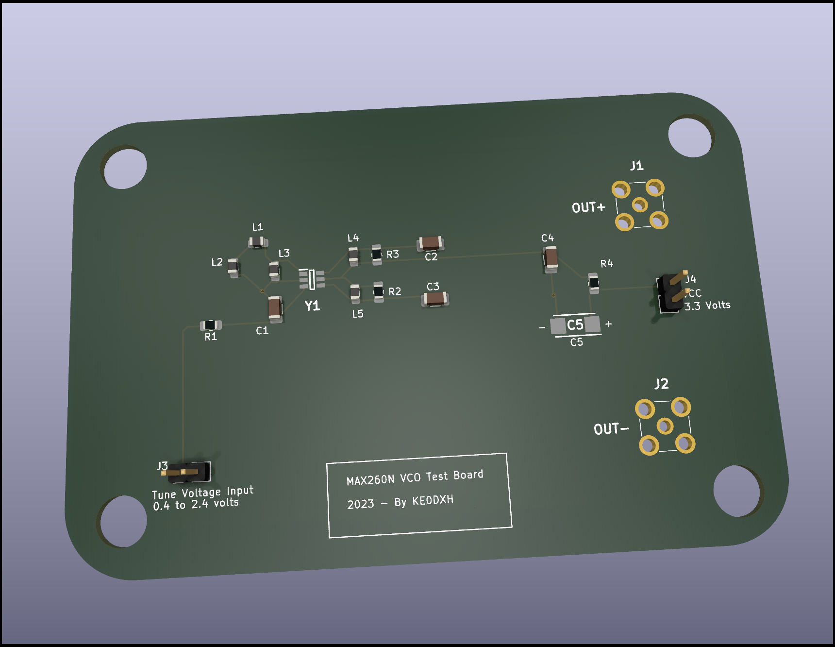
Analog Devices is selling their eval boards for over $200 USD, and the part itself is just a couple of bucks. I'm just getting started desiging my own hardware, so I figured I might as well practice my board design skills. I simply copied The eval board design taken from the Analog Devices website. I included placeholders for all of the resistors and inductors called out in that design, so this board should work for testing all versions of the chip from the MAX2605 to the MAX2609.
I ordered 5 of these from JLCPCB. It was a very simple process. I simply took the contents of the gerbers folder, zipped them up and uploaded the zipfile, and for $40 USD (including shipping), and about 2 weeks, I have a set of boards.
The version of the boards I ordered was commit 27e65ae6c2ac64e3f9bb4, which I later noticed had a few things missing from the silkscreen, and I forgot to do the mounting holes. I fixed those things, and that is the main HEAD commit.
So for about $12 USD total per board (board and parts), I now have 5 of these test boards.
If these devices pan out, I may use them in some future designs I am thinking through.
| Qty | Value | Footprint | References |
|---|---|---|---|
| 2 | 1000 pf | Capacitor_SMD:C_1206_3216Metric | C1, C4 |
| 2 | 120 nH | Inductor_SMD:L_0805_2012Metric | L4, L5 |
| 2 | 3 pf | Capacitor_SMD:C_1206_3216Metric | C2, C3 |
| 2 | PCB.SMAFRA.HT | Mouser:PCBSMAFRAHT | J1, J2 |
| 2 | ~ | Inductor_SMD:L_0805_2012Metric | L1, L2 |
| 2 | ~ | Resistor_SMD:R_0805_2012Metric_Pad1.20x1.40mm_HandSolder | R2, R3 |
| 1 | 10 Ohms | Resistor_SMD:R_0805_2012Metric_Pad1.20x1.40mm_HandSolder | R4 |
| 1 | 10 uF | Mouser:CAPPM6032X280N | C5 |
| 1 | 270 Ohms | Resistor_SMD:R_0805_2012Metric_Pad1.20x1.40mm_HandSolder | R1 |
| 1 | 68 nH | Inductor_SMD:L_0805_2012Metric | L3 |
| 1 | MAX2607EUT+T | Mouser:SOT95P280X145-6N | Y1 |
| 1 | Tune Voltage Input | Connector_PinHeader_2.54mm:PinHeader_1x02_P2.54mm_Vertical | J3 |
| 1 | VCC | Connector_PinHeader_2.54mm:PinHeader_1x02_P2.54mm_Vertical | J4 |

hackclub/OnBoard
💡 Join 1,000 teenagers and make your first PCB with a $100 grant!

polpo/picogus
Emulation of ISA sound cards and CD-ROM on Raspberry Pi Pico (GUS, SB/Adlib, MPU-401, Tandy, CMS, Panasonic CD-ROM) with USB mouse/joystick support


nkitanov/iaq_board
IAQ Board is a DIY (Do-It-Yourself) device for measuring internal air quality


Ardumower/ardumower
Develop an open source robotic lawn mower (HW+SW reference platform)

zmaker/arduino_cookbook
gli sketch del nuovo progetto Arduino Cookbook e dei video di YouTube
It measures 101.6 × 67.7 mm and has 2 copper layers, 1.6 mm thick.
19 parts, built around the MAX2607EUT+T. The full list of its parts is on this page, with links to each part's symbol and footprint where PCBKit's library has them.
From the savagesmc/vcotestboard repository on GitHub, at the commit this page was made from: the board is VCO_Test_Board.kicad_pcb and its schematic VCO_Test_Board.kicad_sch. PCBKit opens the board in the browser, with nothing to install.
Its repository publishes it under the GPL-3.0 licence: you may reuse it on that licence's terms (keep the author's notice, and for a copyleft licence share your changes alike).