

2 layers79 × 84.5 mm

 SatcomRadio/DiseqC_Controller2
Controller board based on a ESP32 to control DiseqC rotors
DiseqController SMD is an open-source printed circuit board by SatcomRadio, from the SatcomRadio/DiseqC_Controller repository on GitHub, published under the MIT licence. It is a 2-layer board of 78 × 29 mm with 26 parts on 30 nets, routed with 127 tracks and 10 vias.
It is built around the TL081CDR2 and AO4484. Its parts include 10 resistors, 3 capacitors, 2 ICs, 2 connectors and 1 transistor. It belongs with the ESP32 boards of this library.
Controller board based on a ESP32 to control DiseqC rotors
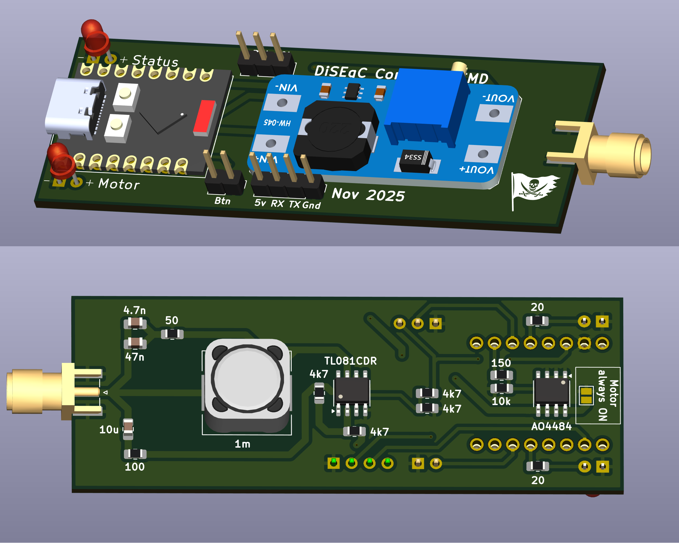
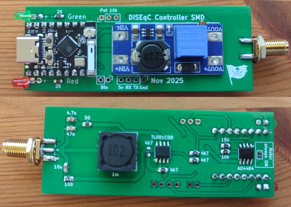
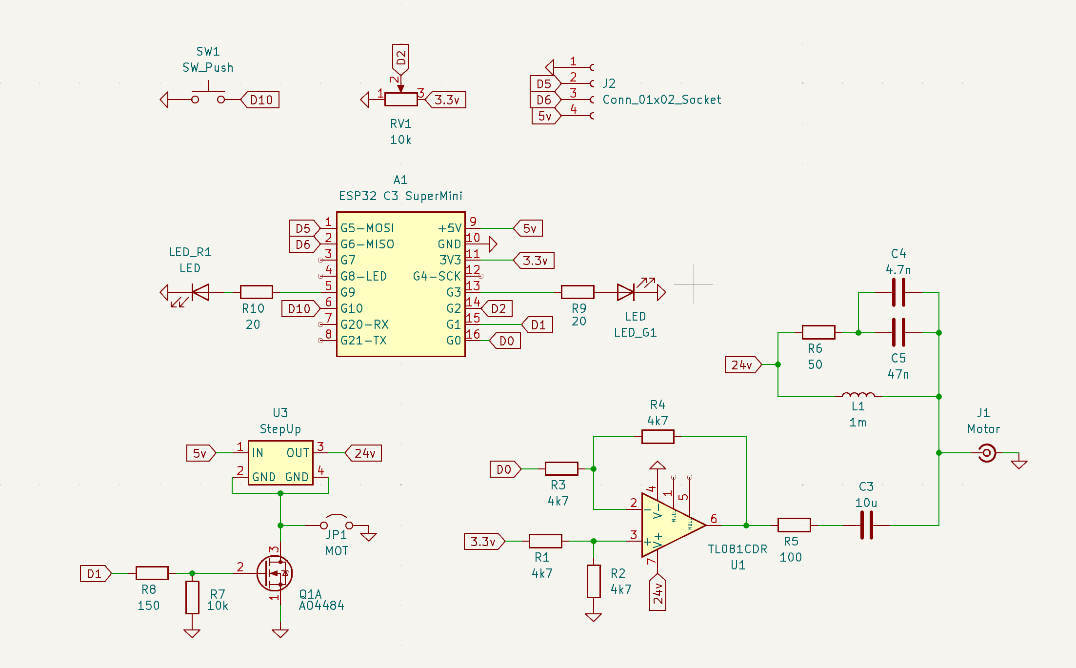
First install nanoframework:
In a powershell window write: dotnet tool install -g nanoff
Check this link for more information
If you want to build the code:
Install nanoframework on the ESP32 C3 with the command:
nanoff --update --target XIAO_ESP32C3 --serialport COM{YOUR NUMBER} --masserase
Then compile the code and upload
If you only want to flash the Diseq controller to your ESP32:
nanoff --target XIAO_ESP32C3 --update --serialport COM{YOUR NUMBER} --deploy --image "c:\PATH_TO_YOUR\DiseqC.bin"
Before connecting the rotor, ADJUST THE VOLTAGE to around 18v max!
To do so, send the command to move the rotor, monitor the voltage in the SMA output and adjust the trimmer.
When turning the controller on the status led will flash fast to indicate that it's trying to connect to your wifi.
When there's no wifi configured or it didn't managed to connect, the ESP32 will create it's own access point and the led will flash slowly.
Connect to it and use the rotor controller at:
http://192.168.5.1
If the controller manages to connect to your wifi, the status led will be on continuously.
Check it's IP address on your modem page.
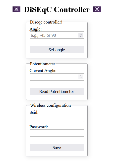
You can also send an angle using a POST to the following API:
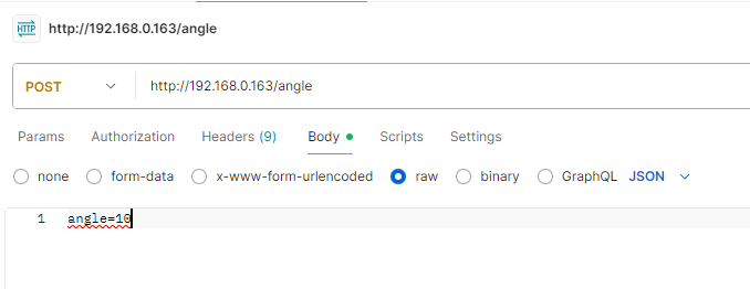
The potentiometer works in intervals of 20º. It's not linear due to limitations of the ESP32 You can check the current value on the website and mark it down with a pen in the metal case.
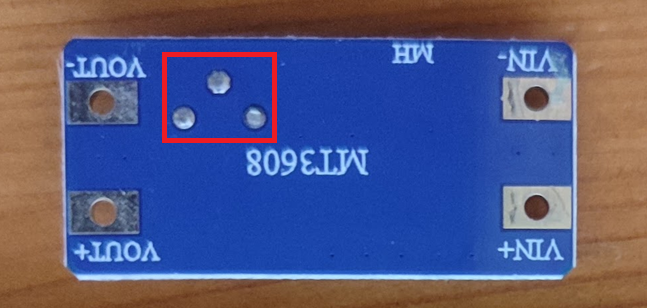
Make sure to trim the solder fillets at the bottom of the step up converter. It's the only difficult part to sodler as you need that it makes a good contact with the tabs at the bottom
Fold the leds before soldering them as shown in previous pictures.
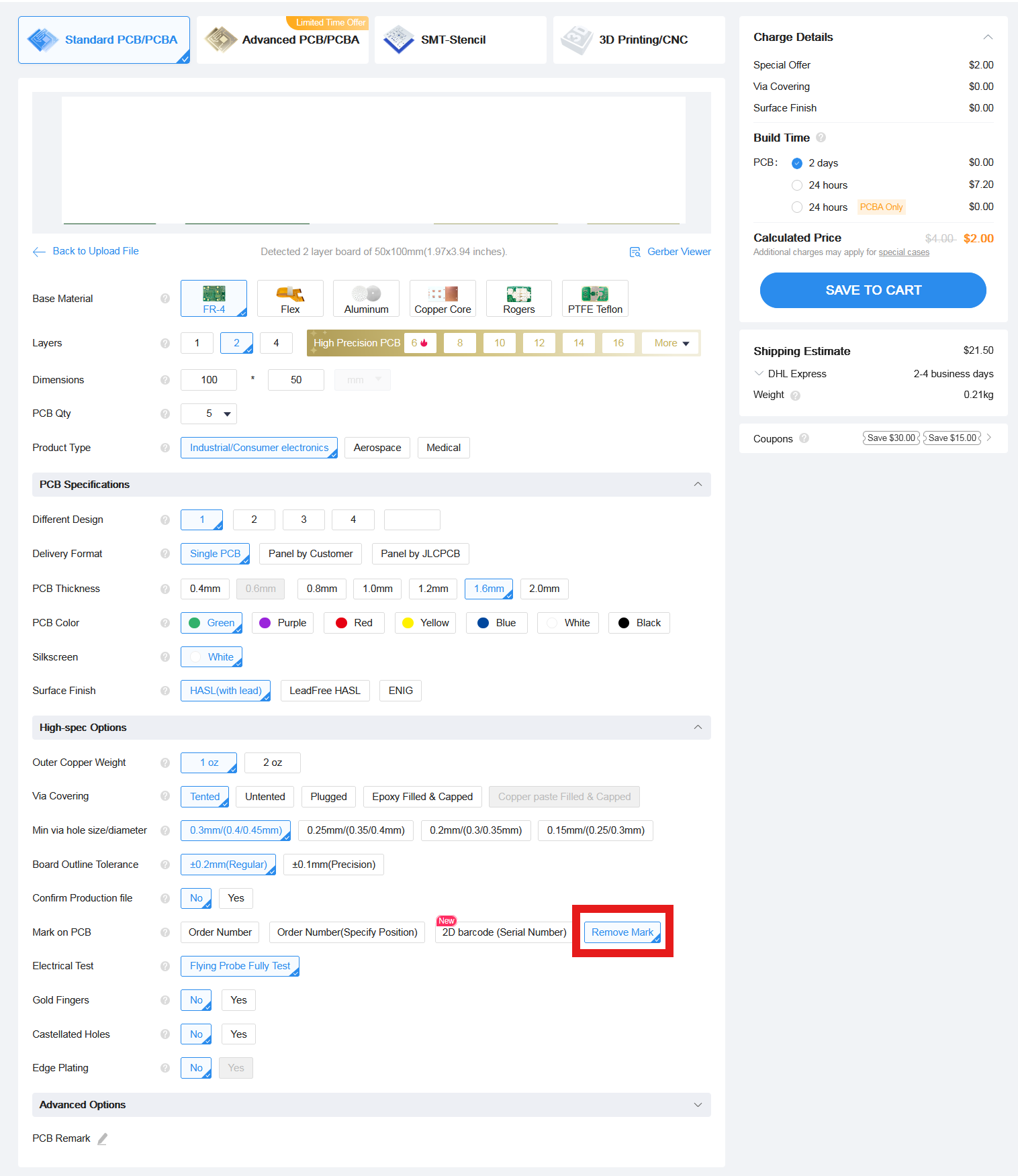
Download the Gerber file from this repo and order it a jlcpcb with the default options.
The only option I've changed is to remove the manufacture code mark
| Qty | Value | Footprint | References |
|---|---|---|---|
| 4 | 4k7 | Resistor_SMD:R_0805_2012Metric_Pad1.20x1.40mm_HandSolder | R1, R2, R3, R4 |
| 2 | 20 | Resistor_SMD:R_0805_2012Metric_Pad1.20x1.40mm_HandSolder | R9, R10 |
| 2 | LED | Footprints:Bent_LED_3mm | LED_G1, LED_R1 |
| 1 | 100 | Resistor_SMD:R_0805_2012Metric_Pad1.20x1.40mm_HandSolder | R5 |
| 1 | 10k | Resistor_SMD:R_0805_2012Metric_Pad1.20x1.40mm_HandSolder | R7 |
| 1 | 10k | Connector_PinHeader_2.54mm:PinHeader_1x03_P2.54mm_Vertical | RV1 |
| 1 | 10u | Capacitor_SMD:C_0805_2012Metric_Pad1.18x1.45mm_HandSolder | C3 |
| 1 | 150 | Resistor_SMD:R_0805_2012Metric_Pad1.20x1.40mm_HandSolder | R8 |
| 1 | 1m | Footprints:Indcutor_12x12mm_H6mm | L1 |
| 1 | 4.7n | Capacitor_SMD:C_0805_2012Metric_Pad1.18x1.45mm_HandSolder | C4 |
| 1 | 47n | Capacitor_SMD:C_0805_2012Metric_Pad1.18x1.45mm_HandSolder | C5 |
| 1 | 50 | Resistor_SMD:R_0805_2012Metric_Pad1.20x1.40mm_HandSolder | R6 |
| 1 | AO4484 | Footprints:AO4484 | Q1 |
| 1 | Conn_01x02_Socket | Connector_PinHeader_2.54mm:PinHeader_1x04_P2.54mm_Vertical | J2 |
| 1 | ESP32 C3 SuperMini | Footprints:ESP32SuperMini | A1 |
| 1 | LOGO | LOGO | G*** |
| 1 | MOT | Jumper:SolderJumper-2_P1.3mm_Open_Pad1.0x1.5mm | JP1 |
| 1 | Motor | Footprints:SMA_Edge | J1 |
| 1 | SW_Push | Connector_PinHeader_2.54mm:PinHeader_1x02_P2.54mm_Vertical | SW1 |
| 1 | StepUp | Footprints:StepUp_2A | U3 |
| 1 | TL081CDR | Package_SO:SOIC-8_3.9x4.9mm_P1.27mm | U1 |
It measures 78 × 29 mm and has 2 copper layers, 1.6 mm thick.
26 parts, built around the TL081CDR2 and AO4484. The full list of its parts is on this page, with links to each part's symbol and footprint where PCBKit's library has them.
From the SatcomRadio/DiseqC_Controller repository on GitHub, at the commit this page was made from: the board is Kicad/DiseqController_SMD.kicad_pcb and its schematic Kicad/DiseqController_SMD.kicad_sch. PCBKit opens the board in the browser, with nothing to install.
Its repository publishes it under the MIT licence: you may reuse it on that licence's terms (keep the author's notice, and for a copyleft licence share your changes alike).

MSzalawiga/Payload-Control-Board
Science Payload Control Board for Queen's Space Engineering Team

yanntalhouarne/ATMEGA324_MTR_DRV_PCB
Isolated motor driver based around the ATMEGA324PB.


hackclub/OnBoard
💡 Join 1,000 teenagers and make your first PCB with a $100 grant!


harbaum/galagino
A Galaga, Pac-Man and Donkey Kong arcade emulator for the ESP32