4 layers92 × 80 mm
Smartlada revB
saschapo/smartlada
Калибровочный стенд PWM на ESP8266 для умного светильника из фонаря ВАЗ-2106 (4x D4184, low-side)
51 parts

 saschapo/smartlada
Калибровочный стенд PWM на ESP8266 для умного светильника из фонаря ВАЗ-2106 (4x D4184, low-side)
Smartlada revC is an open-source printed circuit board by saschapo, from the saschapo/smartlada repository on GitHub. It is a 2-layer board of 100 × 59 mm with 70 parts on 58 nets, routed with 336 tracks and 40 vias.
It is built around the CH224K, TPS54202DDC and ESP32-C6-WROOM-1-N16, with the USBLC6-2SC6 and AOD4184A among its other parts. Its parts include 21 resistors, 11 capacitors, 8 connectors, 6 diodes and 4 ICs. It belongs with the ESP32 and RISC-V boards of this library.


Firmware and custom hardware for a "smart" VAZ-2106 tail light: PWM dimming of the four lamps (turn / brake / marker / reverse) with a local OLED menu, animation effects, and Zigbee control from a Yandex Station (Alice). Runs on a custom board that drops into the light housing and is powered over USB-C PD.
Project page: smartlada.saschapo.me (source in site/).
The current, primary firmware is SmartLadaRevC/ — it targets the
Rev C product board and is what the project ships. Everything else in the tree is either
the hardware design or earlier development stages (see Lineage).
ESP32-C6-WROOM-1 firmware for the Rev C board. Four PWM lamp channels (low-side MOSFET,
gamma + soft-start), an OLED menu with four buttons, pluggable effects, and a Zigbee end
device exposing five endpoints to Alice (four individual lamps + a "Fara" master/effects
device). Local control and Zigbee share one state (config::s, last-writer-wins).
Full details: SmartLadaRevC/README.md.
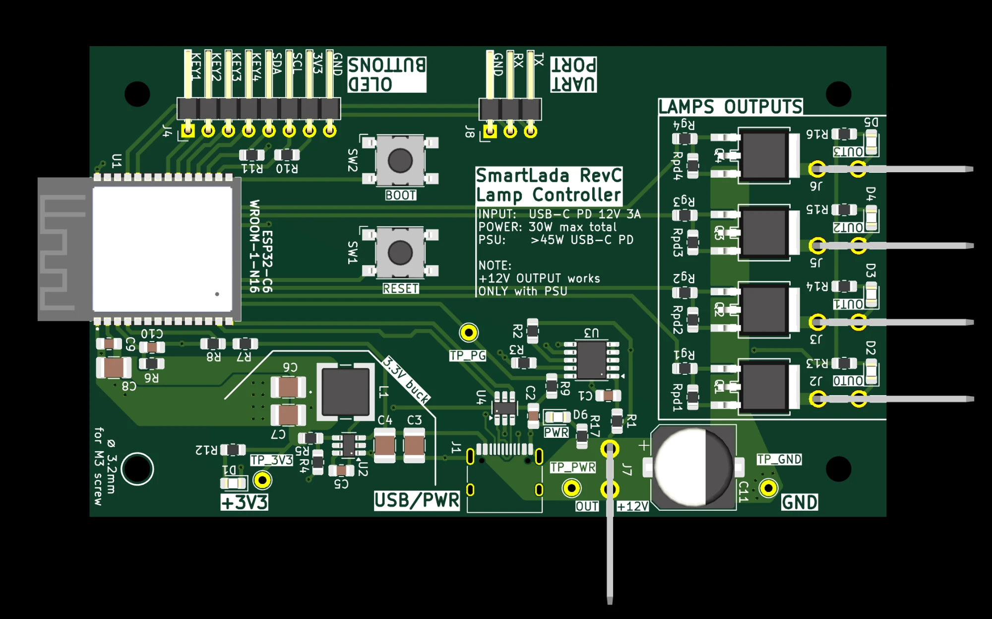
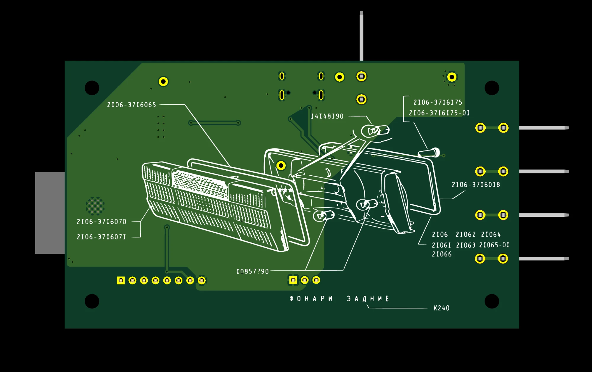
Rev C, KiCad render. Top: ESP32-C6 module, buck, PD trigger, four lamp MOSFETs with Faston outputs. Bottom: the silkscreen carries the VAZ-2106 tail-light exploded view from the parts catalogue ("ФОНАРИ ЗАДНИЕ").
Board design (KiCad, BOM, fabrication): custom_pcb/smartlada_revC/.
Zigbee end-device build, Serial over native USB:
FQBN="esp32:esp32:esp32c6:ZigbeeMode=ed,PartitionScheme=zigbee_8MB,CDCOnBoot=cdc,FlashSize=16M"
arduino-cli compile -b "$FQBN" SmartLadaRevC
arduino-cli upload  -b "$FQBN" -p /dev/cu.usbmodemXXXX SmartLadaRevC
Bench variant with the 2.4" TFT + encoder module in place of the OLED + keys: build flag
UI_TFT, see SmartLadaRevC/README.md.
Plan and resume notes: SmartLadaRevC/DEV_PLAN.md,
SmartLadaRevC/SESSION_HANDOFF.md.
The firmware grew through several stages; the earlier ones are kept for reference:
sketches/SmartLada/ — first bring-up bench on an ESP8266
(calibration, OLED). Its channels/ and config/ layers seeded the ESP32 port.SmartLadaC6/ — ESP32-C6 on a MuseLab nanoESP32-C6 dev board:
LEDC PWM, Wi-Fi AP + web UI, test modes. First C6 firmware.SmartLadaRevB/ — display-based firmware (OLED menu + effects) on the
Rev B board; direct predecessor to Rev C (Rev C forks its src/ layers).SmartLadaRevC/ — current product firmware (this board + Zigbee).Hardware history lives under custom_pcb/ (Rev A → Rev B → Rev C);
research and architecture notes under research/; experimental sketches
under sketches/.
Historical planning/context documents, kept in Russian on purpose:
PROJECT_2106_SMART_LIGHT.md — decisions, hardware, architecture, plan.VAZ2106_Smart_Lamp_Context.md — earlier context document.TASK_smartlada_bench_esp8266.md — ESP8266 bench spec (done).schematic_2106_ESP32.md — early wiring schematic.Chat and
.mddocumentation are in Russian; firmware code, comments, and identifiers are in English.
| Qty | Value | Footprint | References |
|---|---|---|---|
| 6 | 100k | Resistor_SMD:R_0805_2012Metric_Pad1.20x1.40mm_HandSolder | R5, R7, Rpd1, Rpd2, Rpd3, Rpd4 |
| 6 | LED | LED_SMD:LED_0805_2012Metric_Pad1.15x1.40mm_HandSolder | D1, D2, D3, D4, D5, D6 |
| 5 | 10k | Resistor_SMD:R_0805_2012Metric_Pad1.20x1.40mm_HandSolder | R2, R6, R9, R10, R11 |
| 5 | 4k7 | Resistor_SMD:R_0805_2012Metric_Pad1.20x1.40mm_HandSolder | R13, R14, R15, R16, R17 |
| 4 | 100R | Resistor_SMD:R_0805_2012Metric_Pad1.20x1.40mm_HandSolder | Rg1, Rg2, Rg3, Rg4 |
| 4 | AOD4184A | Vendor:TO252_AOS | Q1, Q2, Q3, Q4 |
| 4 | MountingHole_3.2mm_M3 | MountingHole:MountingHole_3.2mm_M3 | HOLE1, HOLE1, HOLE1, HOLE1 |
| 3 | 100nF | Capacitor_SMD:C_0805_2012Metric_Pad1.18x1.45mm_HandSolder | C2, C5, C9 |
| 3 | 22uF | Capacitor_SMD:C_1210_3225Metric_Pad1.33x2.70mm_HandSolder | C6, C7, C8 |
| 2 | 10uF | Capacitor_SMD:C_1210_3225Metric_Pad1.33x2.70mm_HandSolder | C3, C4 |
| 2 | 1k | Resistor_SMD:R_0805_2012Metric_Pad1.20x1.40mm_HandSolder | R1, R12 |
| 2 | 1uF | Capacitor_SMD:C_0805_2012Metric_Pad1.18x1.45mm_HandSolder | C1, C10 |
| 1 | +12V | Vendor:TE_1217754-1 | J7 |
| 1 | 10uH | Vendor:IND_CDRH6D28NP-100NC_SUM | L1 |
| 1 | 22k | Resistor_SMD:R_0805_2012Metric_Pad1.20x1.40mm_HandSolder | R4 |
| 1 | 24k | Resistor_SMD:R_0805_2012Metric_Pad1.20x1.40mm_HandSolder | R3 |
| 1 | 33k | Resistor_SMD:R_0805_2012Metric_Pad1.20x1.40mm_HandSolder | R8 |
| 1 | 470uF | Capacitor_SMD:CP_Elec_10x10.5 | C11 |
| 1 | BOOT | Button_Switch_SMD:SW_SPST_Omron_B3FS-100xP | SW2 |
| 1 | CH224K | Package_SO:SSOP-10-1EP_3.9x4.9mm_P1mm_EP2.1x3.3mm_ThermalVias | U3 |
| 1 | ESP32-C6-WROOM-1-N16 | Vendor:XCVR_ESP32-C6-WROOM-1-N16 | U1 |
| 1 | J_UART | Connector_PinHeader_2.54mm:PinHeader_1x03_P2.54mm_Horizontal | J8 |
| 1 | LOGO | LOGO | G*** |
| 1 | OLED_AND_BUTTONS | Connector_PinHeader_2.54mm:PinHeader_1x08_P2.54mm_Horizontal | J4 |
| 1 | OUT0 | Vendor:TE_1217754-1 | J2 |
| 1 | OUT1 | Vendor:TE_1217754-1 | J3 |
| 1 | OUT2 | Vendor:TE_1217754-1 | J5 |
| 1 | OUT3 | Vendor:TE_1217754-1 | J6 |
| 1 | RESET | Button_Switch_SMD:SW_SPST_Omron_B3FS-100xP | SW1 |
| 1 | TPS54202DDC | Package_TO_SOT_SMD:SOT-23-6_Handsoldering | U2 |
| 1 | TP_3V3 | TestPoint:TestPoint_THTPad_D2.0mm_Drill1.0mm | TP3 |
| 1 | TP_GND | TestPoint:TestPoint_THTPad_D2.0mm_Drill1.0mm | TP1 |
| 1 | TP_PG | TestPoint:TestPoint_THTPad_D2.0mm_Drill1.0mm | TP4 |
| 1 | TP_PWR | TestPoint:TestPoint_THTPad_D2.0mm_Drill1.0mm | TP2 |
| 1 | USBLC6-2SC6 | Package_TO_SOT_SMD:SOT-23-6_Handsoldering | U4 |
| 1 | USB_C_16P | Connector_USB:USB_C_Receptacle_HRO_TYPE-C-31-M-12 | J1 |
saschapo/smartlada
Калибровочный стенд PWM на ESP8266 для умного светильника из фонаря ВАЗ-2106 (4x D4184, low-side)

saschapo/smartlada
Калибровочный стенд PWM на ESP8266 для умного светильника из фонаря ВАЗ-2106 (4x D4184, low-side)

Xerolux/IDM-Smart-Climate-Platform
Diese Platine empfängt Temperatur- und Feuchtewerte aus Home Assistant und simuliert gegenüber der IDM AERO ALM den originalen Temperatur-/Feuchtesensor.

makespacemadrid/cheap-wled-controller
WLED controller, for practising SMD soldering

Haxintosh/tiled-pcb-heater
Scalable and modular 3D printer heated bed


tomrodinger/RS485_Controller
This integrates an ESP32-S3 module with an RS485 interface, so that it can be used to control Gearotons Servomotors or other RS485 devices

ChladpavPy/Super3DMaker
So first I want to explain, why I started this project. I had an old Profi3DMaker 3D printer at home, which was not used for a long time, mainly because of the hardware, which was just outdated.


lhm0/rotating_display_color
56 LED rotating color display with RP2040 and ESP32 microcontrollers
It measures 100 × 59 mm and has 2 copper layers, 1.6 mm thick.
70 parts, built around the CH224K, TPS54202DDC, ESP32-C6-WROOM-1-N16 and USBLC6-2SC6. The full list of its parts is on this page, with links to each part's symbol and footprint where PCBKit's library has them.
From the saschapo/smartlada repository on GitHub, at the commit this page was made from: the board is custom_pcb/smartlada_revC/smartlada_revC.kicad_pcb and its schematic custom_pcb/smartlada_revA/smartlada_revA.kicad_sch. PCBKit opens the board in the browser, with nothing to install.
Its repository states no licence, so its author keeps all rights: ask saschapo before reusing the design.