2 layers44.5 × 72.7 mm
OSO SWAT C1-jig
joeycastillo/Sensor-Watch
A board replacement for the classic Casio F-91W wristwatch
28 parts2.1k
 sarweiler/jamloopy-ctrl
A controller for the Atari 2600 JamLoopy music app
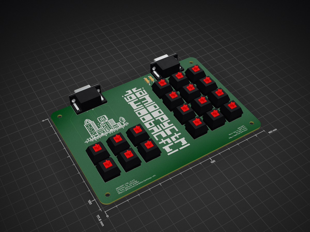
Jamloopy ctrl is an open-source printed circuit board by sarweiler, from the sarweiler/jamloopy-ctrl repository on GitHub. It is a 2-layer board of 160 × 111.8 mm with 28 parts on 14 nets, routed with 107 tracks and 0 vias.
Its parts include 2 resistors and 2 connectors. It belongs with the retro computing and games boards of this library.
JamLoopy Ctrl is a controller for the Atari 2600 music app JamLoopy by Zden Hlinka. It's basically an Atari joystick circuit and an Atari keyboard controller circuit on a single PCB.
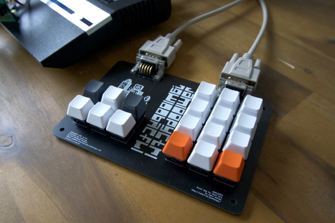
Building a JamLoopy Ctrl is a very easy and beginner-friendly soldering project.
Download the jamloopy-ctrl-gerbers.zip file for the latest release, upload the zip archive to a PCB manufacturer of your choice, and order a PCB. Usually the default settings for the PCBs are okay – just choose a color for the solder mask that you like, if you dont want the standard PCB-green.
Using the controller is pretty straight forward: Connect the left port of your controller to the left joystick port on the Atari and the right port to the right joystick port on the Atari using two DB9 extension cables.
On the left side of the controller you've got a joystick in the form of cursor keys (UP1, DOWN1, LEFT1, and RIGHT1 on the PCB) and two fire buttons (FIRE1 and FIRE2 on the PCB). The fire buttons are identical, I just added a second one for symmetry reasons.
On the right side of the controller you've got an Atari keyboard controller with switches 1 to 9 and 0 (SW1 to SW9 and SW11), the *-key (SW10) and the #-key (SW12).
For information on how to use JamLoopy, check out the JamLoopy manual.

Build and use JamLoopy Ctrl at your own risk. I cannot be held responsible for damage caused to your devices, yourself or others.
This work is licensed under CC-BY-SA 4.0.

| Qty | Value | Footprint | References |
|---|---|---|---|
| 18 | SW_Push | Button_Switch_Keyboard:SW_Cherry_MX_1.00u_PCB | DOWN1, FIRE1, FIRE2, LEFT1, RIGHT1, SW1, SW2, SW3, SW4, SW5, SW6, SW7, SW8, SW10, SW11, SW12 +2 |
| 1 | 4.7K | Resistor_THT:R_Axial_DIN0207_L6.3mm_D2.5mm_P10.16mm_Horizontal | R2 |
| 1 | Joystick left | Connector_Dsub:DSUB-9_Female_Horizontal_P2.77x2.84mm_EdgePinOffset9.90mm_Housed_MountingHolesOffset11.32mm | J1 |
| 1 | Joystick right | Connector_Dsub:DSUB-9_Female_Horizontal_P2.77x2.84mm_EdgePinOffset9.90mm_Housed_MountingHolesOffset11.32mm | J2 |
| 1 | LOGO | jamloopy:jamloopy_pcb | G*** |
| 1 | LOGO | jamloopy:city | G*** |
| 1 | R4.7K | Resistor_THT:R_Axial_DIN0207_L6.3mm_D2.5mm_P10.16mm_Horizontal | R1 |
The 24 most common of 28 parts.
It measures 160 × 111.8 mm and has 2 copper layers, 1.6 mm thick.
28 parts. The full list of its parts is on this page, with links to each part's symbol and footprint where PCBKit's library has them.
From the sarweiler/jamloopy-ctrl repository on GitHub, at the commit this page was made from: the board is kicad/jamloopy-ctrl.kicad_pcb. PCBKit opens the board in the browser, with nothing to install.
Its repository states no licence, so its author keeps all rights: ask sarweiler before reusing the design.
joeycastillo/Sensor-Watch
A board replacement for the classic Casio F-91W wristwatch

TalismanDesign/PocketMage_PDA
An E-Ink PDA device using the ESP32 S3.

rusefi/rusefi
rusefi - GPL internal combustion engine control unit

hackclub/OnBoard
💡 Join 1,000 teenagers and make your first PCB with a $100 grant!

asterics/esp32_mouse_keyboard
ESP32 implementation for HID over GATT Keyboard and Mouse (Bluetooth Low Energy). Including serial API for external modules (similar to Adafruit EZKey HID)


Luos-io/luos_engine
Open-source and real-time orchestrator for cyber-physical-systems, to easily design, test and deploy embedded applications and digital twins.

Chrismettal/EleLab_v2
Cheap DIY lab system for hobbyists and the tinkering folk