
2 layers50 × 35 mm

 samir-souza/minibots12
Cool DIY robots for your amazing project
Minibots is an open-source printed circuit board by samir-souza, from the samir-souza/minibots repository on GitHub, published under the CC-BY-SA-4.0 licence. It is a 2-layer board of 20.6 × 49.3 mm with 17 parts on 24 nets, routed with 220 tracks and 0 vias.
Its parts include 7 connectors, 3 capacitors, 3 ICs, 2 resistors and 1 diode. It belongs with the robots and motor control boards and the ESP8266 boards of this library.
Minibots is based on a very popular and cheap uController, the . So, the PCB is basically this uController connected to two servos (controlled by PWM) and other elements, like the classic accelerometer+gyroscope MPU6050, external pins, control LED, etc.
The PCB was created with v4.0.2+dfsg1-stable and you can see the KiCad project in this directory. The Gerber files can also be found in this dir. In order to manufacture a new PCB for you Minibot, you can use the Gerber files. If you never created a PCB before, you can use some online services that you just upload the Gerber files, pay for the boards and you then receive the boards at your home. The project is very simple. It has just one layer and you can make tracks with copper 2Oz.
| PCB Layout | Connections | Top | Bottom |
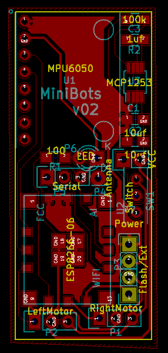 | 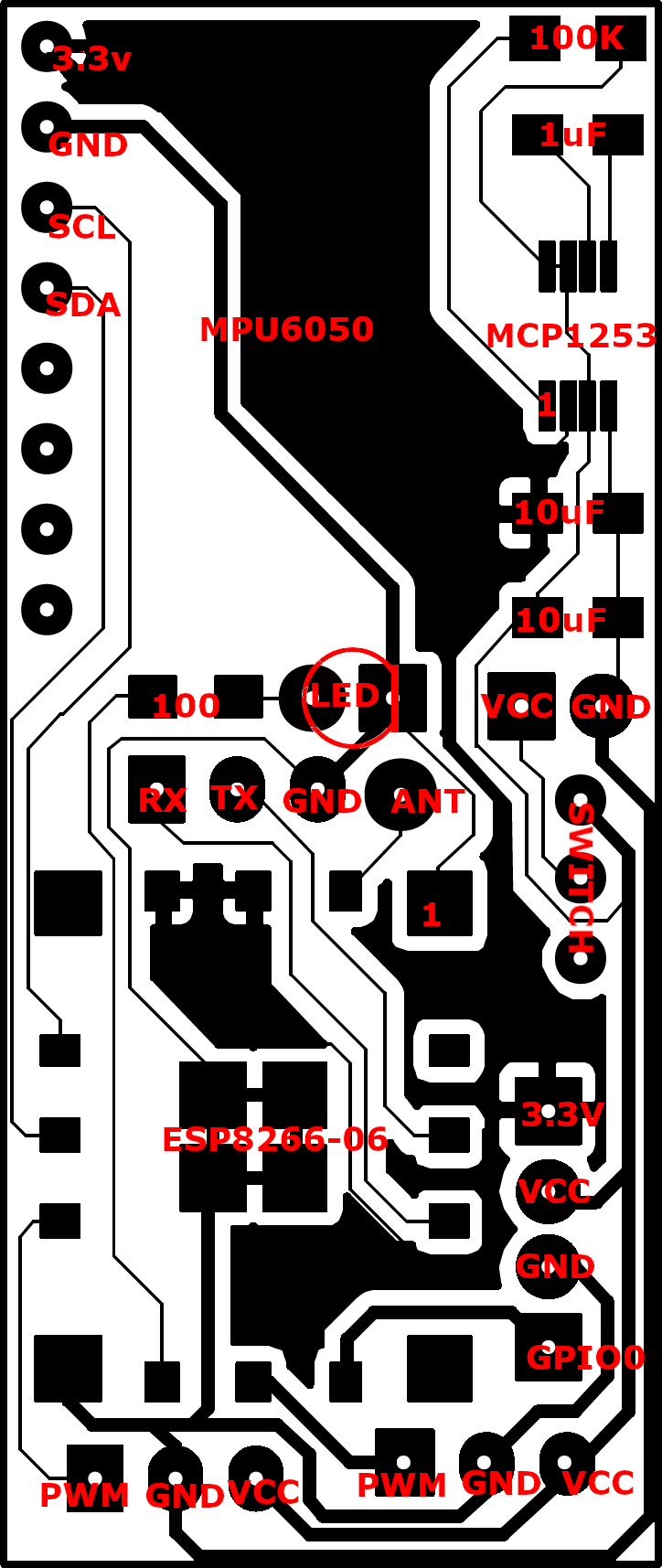 | 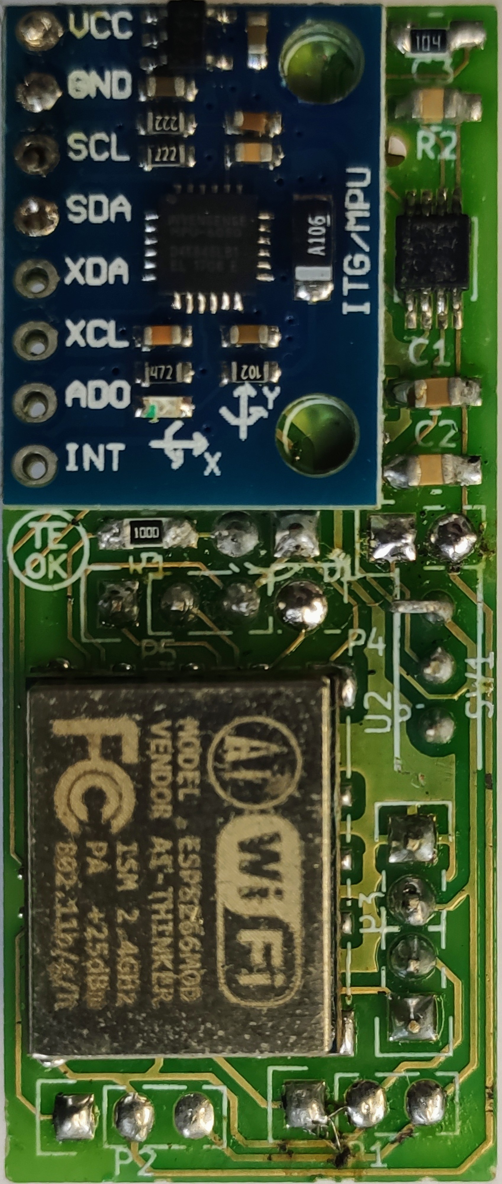 | 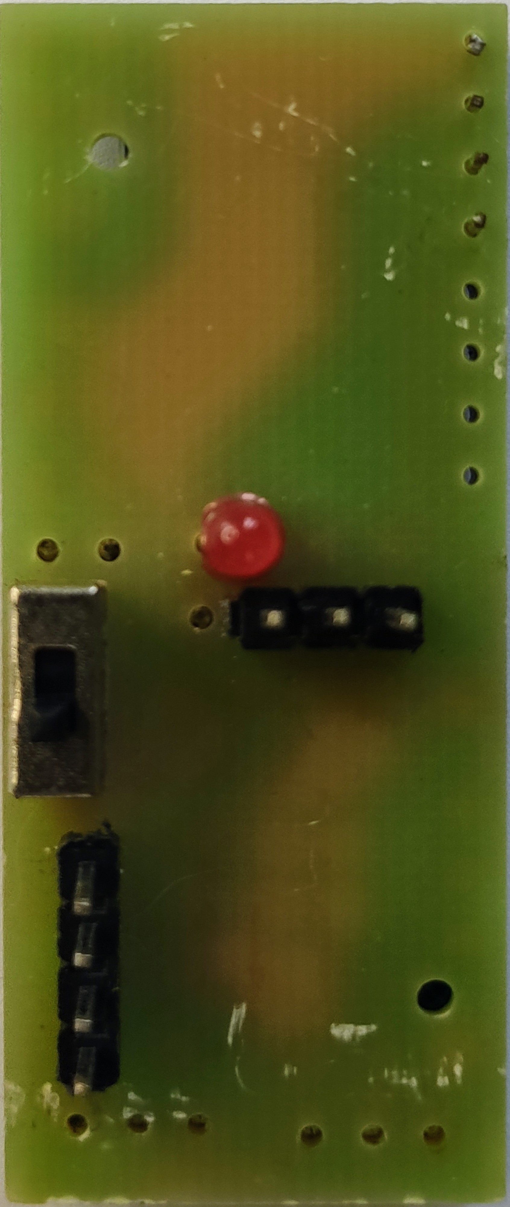 |
As you can see above, the layout is very simple and the list of components (BOM) is:
You need to have some soldering skills to put all the components on the board. The uController requires an SMD soldering station, but the rest of the components can be soldered by just using a normal iron.
Micro Servo 9g SG90 is a 180 degrees servo. You need to hack it to transform it into a continuous servo (360 degrees). There are tons of tutorials on the Internet teaching how to do that. Here it is an example: https://rookieelectronics.com/servohack/
MCP1253 is a power pump, it improves the battery energy utilization and also works as a power regulation. It's mandatory to keep the correct voltage (3.3v) all the time to the uController. It also works as a power isolation, given the servos are connected directly to the battery and the rest of the circuit is feed by the power pump.
ESP8266 package 04 was used in the original project, but this packaging was discontinued, so, in v02 (this version) the package 06 was used. It is easier to find on the Internet but it is more difficult to be soldered, given it requires a Rework station (SMD soldering machine with hot air).
SMD is important to keep the size of the board in general. You can see that all the resistors and capacitors are SMD 0805.
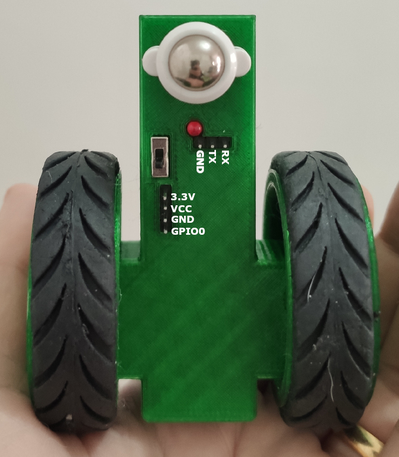
Bottom view of the Minibot after finishing the assembly in the 3D printed Chassis:
| Qty | Value | Footprint | References |
|---|---|---|---|
| 2 | 10uf | Capacitors_SMD:C_0805_HandSoldering | C1, C2 |
| 1 | 100 | Resistors_SMD:R_0805_HandSoldering | R1 |
| 1 | 100k | Resistors_SMD:R_0805_HandSoldering | R2 |
| 1 | 1uf | Capacitors_SMD:C_0805_HandSoldering | C3 |
| 1 | Antenna | Pin_Headers:Pin_Header_Straight_1x01 | P4 |
| 1 | ESP8266-06 | ESP8266:ESP-06 | U2 |
| 1 | Flash/Ext | Pin_Headers:Pin_Header_Straight_1x02 | P3 |
| 1 | LED | LEDs:LED-3MM | D1 |
| 1 | LeftMotor | Pin_Headers:Pin_Header_Straight_1x03 | P1 |
| 1 | MCP1253 | Housings_SSOP:MSOP-8_3x3mm_Pitch0.65mm | U3 |
| 1 | MPU6050 | minibots:MPU6050 | U1 |
| 1 | Power | Pin_Headers:Pin_Header_Straight_1x02 | P7 |
| 1 | RightMotor | Pin_Headers:Pin_Header_Straight_1x03 | P2 |
| 1 | Serial | Pin_Headers:Pin_Header_Straight_1x03 | P5 |
| 1 | Switch | minibots:MiniSlideSwitch | SW1 |
| 1 | VCC | Pin_Headers:Pin_Header_Straight_1x02 | P6 |


hoglet67/RGBtoHDMI
Bare-metal Raspberry Pi project that provides pixel-perfect sampling of Retro Computer RGB/YUV video and conversion to HDMI


hackclub/OnBoard
💡 Join 1,000 teenagers and make your first PCB with a $100 grant!

DDeGonge/OS-ARM
This arm is not industrial and it will not be fast, but that is not my goal. But it will hopefully be a very nice looking arm fully capable of 6dof motion, cheap enough to keep it accessable but capable enough to…


It measures 20.6 × 49.3 mm and has 2 copper layers, 1.6 mm thick.
17 parts. The full list of its parts is on this page, with links to each part's symbol and footprint where PCBKit's library has them.
From the samir-souza/minibots repository on GitHub, at the commit this page was made from: the board is 02_BotPCB/Minibots.kicad_pcb. PCBKit opens the board in the browser, with nothing to install.
Its repository publishes it under the CC-BY-SA-4.0 licence: you may reuse it on that licence's terms (keep the author's notice, and for a copyleft licence share your changes alike).