
2 layers22.2 × 46.4 mm
C64-Switchless Quad Kernal Switcher
bwack/C64-Switchless-Multi-Kernal-27C256-adapter
Kernal switcher for the C64/C64C/C128
14 parts112
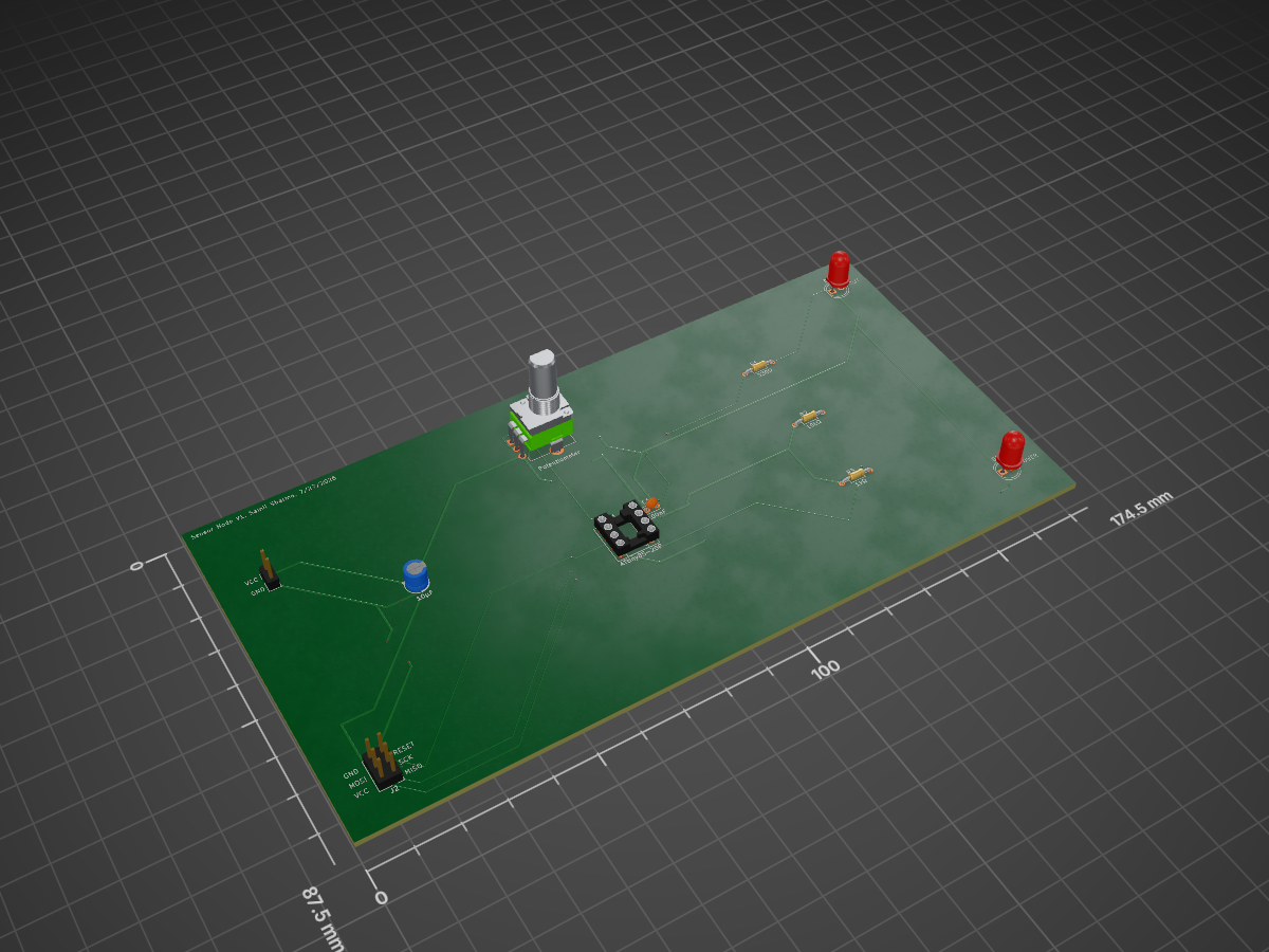
 samils2/attiny85-sensor-node
A small through-hole PCB built around an ATtiny85 that reads a potentiometer with the on-chip ADC and drives an LED output.
Capstone is an open-source printed circuit board by samils2, from the samils2/attiny85-sensor-node repository on GitHub. It is a 2-layer board of 174.5 × 87.5 mm with 11 parts on 10 nets, routed with 152 tracks and 17 vias.
It is built around the ATTINY85-20PU. Its parts include 3 resistors, 2 capacitors, 2 diodes, 2 connectors and 1 IC. It belongs with the AVR (ATmega, ATtiny) boards of this library.
A small through-hole PCB built around an ATtiny85 that reads a potentiometer with the on-chip ADC and drives an LED output. I designed it in KiCad as the capstone of a self-directed electronics curriculum covering circuit fundamentals, digital logic, and PCB design workflow.
The board has four main parts:
I used through-hole components throughout so the board can be hand-soldered.
Pin conflict between the potentiometer and SCK. My first layout put the potentiometer wiper on a pin that also serves as SCK for in-system programming, which would have interfered with flashing the chip. I moved the wiper to PB3 so the ADC input and the ISP header no longer share a pin.
Decoupling capacitor wiring. While checking the schematic I found wiring errors in my decoupling capacitor connections and corrected them so the capacitor sits across the supply pins as intended.
RESET pull-up. I added a pull-up resistor on RESET so the chip does not reset from noise during normal operation.
Power indicator LED. I added an LED on the supply rail so I can confirm power with a quick glance before probing.
Net labels for ISP routing. I used net labels instead of long wires for the programming header connections to keep the schematic readable.
Ground pour. The board has a GND copper pour to give a low-impedance return path and simplify routing.
Through-hole parts. Every component is through-hole for easy hand-soldering.
| Part | Notes |
|---|---|
| ATtiny85-20PU | DIP-8 microcontroller |
| DIP-8 machined-pin socket | Lets the chip be removed and reprogrammed |
| Alpha RD901F-40 potentiometer | Analog input |
| 10 µF electrolytic capacitor | |
| Pin headers | ISP programming header |
| LEDs and resistors | 330, 1k, & 10k Ω |
| USBasp programmer | For flashing (not part of the board) |
Samil Sharma, Mechanical Engineering at UIUC (pursuing ECE) | https://www.linkedin.com/in/samil-sharma-a38b2a301/
| Qty | Value | Footprint | References |
|---|---|---|---|
| 2 | LED | LED_THT:LED_D5.0mm | D1, D2 |
| 1 | 100nF | Capacitor_THT:C_Disc_D3.0mm_W2.0mm_P2.50mm | C1 |
| 1 | 10kΩ | Resistor_THT:R_Axial_DIN0204_L3.6mm_D1.6mm_P7.62mm_Horizontal | R2 |
| 1 | 10μF | Capacitor_THT:CP_Radial_D5.0mm_P2.00mm | C2 |
| 1 | 1kΩ | Resistor_THT:R_Axial_DIN0204_L3.6mm_D1.6mm_P7.62mm_Horizontal | R3 |
| 1 | 330Ω | Resistor_THT:R_Axial_DIN0204_L3.6mm_D1.6mm_P7.62mm_Horizontal | R1 |
| 1 | ATtiny85-20P | Package_DIP:DIP-8_W7.62mm_Socket | U1 |
| 1 | Conn_01x02_Pin | Connector_PinHeader_2.54mm:PinHeader_1x02_P2.54mm_Vertical | J1 |
| 1 | Conn_02x03_Counter_Clockwise | Connector_PinHeader_2.54mm:PinHeader_2x03_P2.54mm_Vertical | J2 |
| 1 | Potentiometer | Potentiometer_THT:Potentiometer_Alpha_RD901F-40-00D_Single_Vertical_CircularHoles | RV1 |
It measures 174.5 × 87.5 mm and has 2 copper layers, 1.6 mm thick.
11 parts, built around the ATTINY85-20PU. The full list of its parts is on this page, with links to each part's symbol and footprint where PCBKit's library has them.
From the samils2/attiny85-sensor-node repository on GitHub, at the commit this page was made from: the board is Hardware/capstone.kicad_pcb and its schematic Hardware/capstone.kicad_sch. PCBKit opens the board in the browser, with nothing to install.
Its repository states no licence, so its author keeps all rights: ask samils2 before reusing the design.
bwack/C64-Switchless-Multi-Kernal-27C256-adapter
Kernal switcher for the C64/C64C/C128

plusvic/simplebus2-intercom
General description of the Simplebus2 protocol used by some Comelit's intercoms. Hardware for retransmitting Simplebus2 messages over UART.

osmocom/osmocom-analog
Software Implementation of analog cellular telephony systems like NMT, TACS, IMTS, A/B/C-Netz; mirror of https://gitea.osmocom.org/cellular-infrastructure/osmocom-analog

strickyak/jerboa-attiny85-mod-synth
Modular Synthesizer using an ATtiny85 chip for each module.


Hack-a-Day/Remoticon_KiCad_Blender
support files for the 2020 Remoticon KiCad to Blender > PCB renders workshop
