2 layers55 × 80 mm
Board esp32 v2
sudomesh/disaster-radio
A (paused) work-in-progress long-range, low-bandwidth wireless disaster recovery mesh network powered by the sun.
101 parts1.1k

 samarjit/MyIMX23331
MyIMX233 will be a homemade Single board computer based on Freescale iMX233 and 64MB DDR2 RAM built with KiCad
MyIMX233 is an open-source printed circuit board by samarjit, from the samarjit/MyIMX233 repository on GitHub. It is a 2-layer board of 74.1 × 92 mm with 101 parts on 133 nets, routed with 7,377 tracks and 136 vias.
Its parts include 42 capacitors, 27 resistors, 10 diodes, 8 connectors and 2 ICs. It belongs with the computers and single-board computers boards of this library.
I am starting to build a single board computer with freescale microprocessor iMX233 128 LQFP and 64MB DDR2 SDRAM in 66TSOP. This single board computer will be bare bones with lots of GPIO exposed. There is no special goal for this project. I am just curious to see if it works. In future I might add an LCD. The PCB is two layered only and can be manufactured cheap.
Cloning this repository should work. It does use opendous conn_fci from https://github.com/cpavlina/kicad-pcblib.git, https://github.com/cpavlina/kicad-schlib.git Copy kicad-pcblib\conn-fci.pretty to KiCad\share\kicad\modules\conn-fci.pretty Add kicad-schlib-master\library\conn-fci.lib to SchematicEditor -> ComponentLibraries Add opendous to component libraries too.
So I have put together a mashup of schematic design of IMX233 and 64MB RAM from freescale reference design and other sources.
Freescale microprocessor:
DDR RAM - I think all these below RAM chips are compatible.
This project is a work in progress and there is no gurantee that I will ever be able to complete it :).
But if you want to try building same stuff as I am building. Go ahead and fork it. Download KiCad. I am using nightly version of it, because it does not require you to export the netlist and import it again in pcb editor. Make the workflow really easy. I can see one bug in KiCAD, which is after modifying the footprint by adding a step file. It looses the saved settings.
Once you have installed KiCAD, open MyIMX233.pro file.
MyIMX233.sch - Schematic file.
MyIMX233.kicad_pcb - PCB
ReferenceSch - contains reference materials. I uploaded all of them for providing content incase someone wants to understand the design.
Few soldering quirks are there. USB pads are quite small to solder. Also pad to hold USB in place is also very small and bad for soldering. Even the SD card pads are also small for soldering. These were new footprints so in next version I will make longer pads for these. RAM pads can be made slightly longer for reliable soldering.
Soldered board and powered up without SD card. Some error were coming 0x80207002. Boot loader looking for I2C and it is not initialized. Turned out to be soldering of one pin was not proper for LQFP128. Fixed this pin issue then SD card missing related errors were coming. Added SD card with bogus data 0x8020A007 - ERROR_DDI_SD_CONFIG_BLOCK_NOT_FOUND. Added SD card formatted properly but still 0x8020A007. Little bit further digging showed that SD card MBR boot is not enabled by default. We need to burn an OPT bit HW_OCOTP_ROM0::SD_MBR_BOOT to enable booting from SD card. This process is irreversible. Default boot mode is BCB. I read up again librecalc's failure blog. It gave two perl programs to burn the SD card with u-boot in BCB mode. The 2nd perl program didn't run as it assumed smaller SD cards only. I edited the perl program to make it find proper boot signatures. Now we can see something HTLC in UART console.
That's too less info to debug further. At this point I posted in freescale community. https://community.nxp.com/message/949934. I decided to blow the MBR OTP flag using BitBurner. Then added MBR based uSD card and same u-boot. Now again it shows HTLC. Good news is that MBR booting works. But it fails very soon. Need bootlets which gives more detailed log instead of u-boot. Turned out voltages are fluctuating all 3v3, 4v2, 1v8, 1v. They were fluctuating in a cycle. I burned official Olinuxino image in SD card. That seems to have bootlets so it gave more info. After right after memory FRAC 0x92926192 it reboots. I heated up all the pins of DDR and iMX233 with soldering iron. It goes 1 more line ahead in log init_ddr_mt46v32m16_133Mhz and sometimes power 0x00820710. I added a big capacitor in place of battery which goes the log to further and says uSD card general error ending with r14<0>HTLLLL... I tried adding a few caps on 3v3. But nothing helped. Then I tried the other jumper of battery mode. Then it started loading kernel.
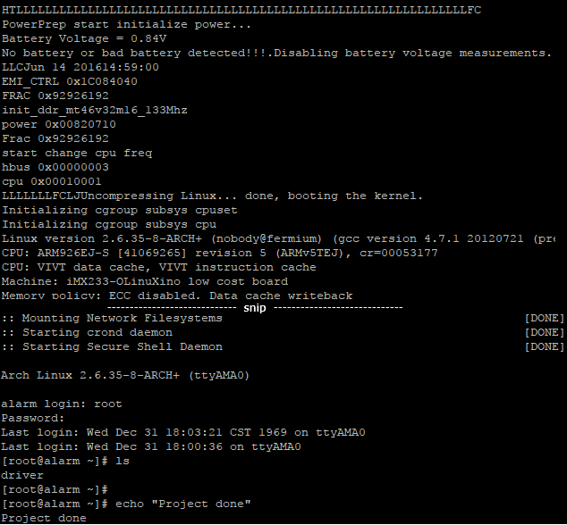
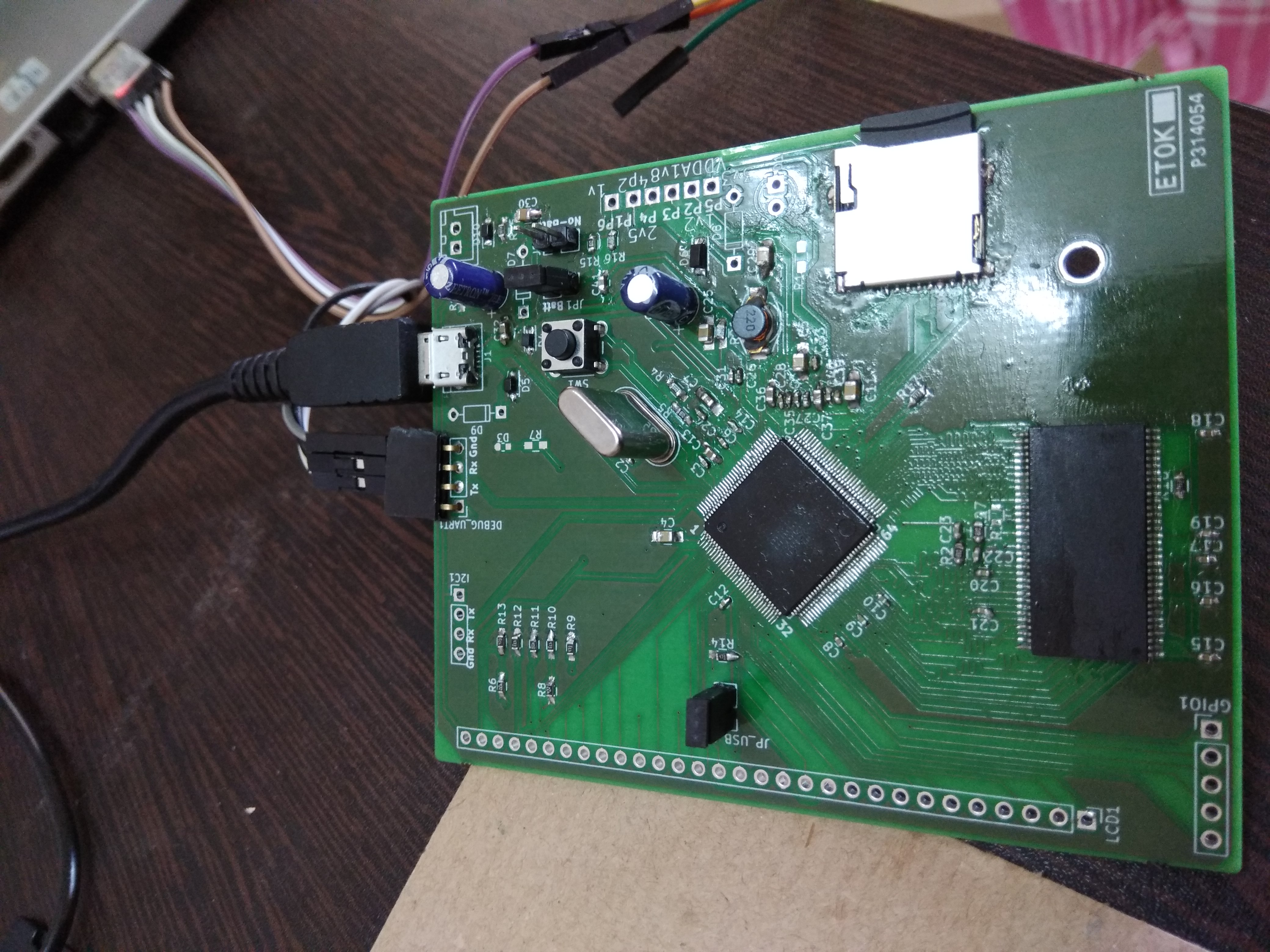
Started modifying the schematic to make battery and USB wall power optional using jumpers. Also realized boot selection can be done using resistors. Sent for fabrication of PCB to pcbpower.
Good news is most of the components fitted. Also I got some confidence about my KiCAD skills.
Some shortcomings were observed, like the pads for soldering were two short for the fine pitched LQFP128 0.4mm pitch and solder mask dams were not created between pads which made it incredibly hard to solder. I will have to customize the LQFP128 footprint to make it suitable for hand soldering. Some 0402 caps were placed very close, I realized the courtyard verification of components is not turned on by default. I had limited success like UART was working USB was working, BitBurner was working and showing all the OPT(One Time Programmable) bits. Some gibberish was coming on UART console. I used solder paste for soldering, so I thought some shorting might be happening. Then I tried to do reflow soldering to make the solder joints liquify once and then quickly cool it using a frying pan. It actually fried my board! I also mistakenly soldered uSD card with power on! Carelessness!
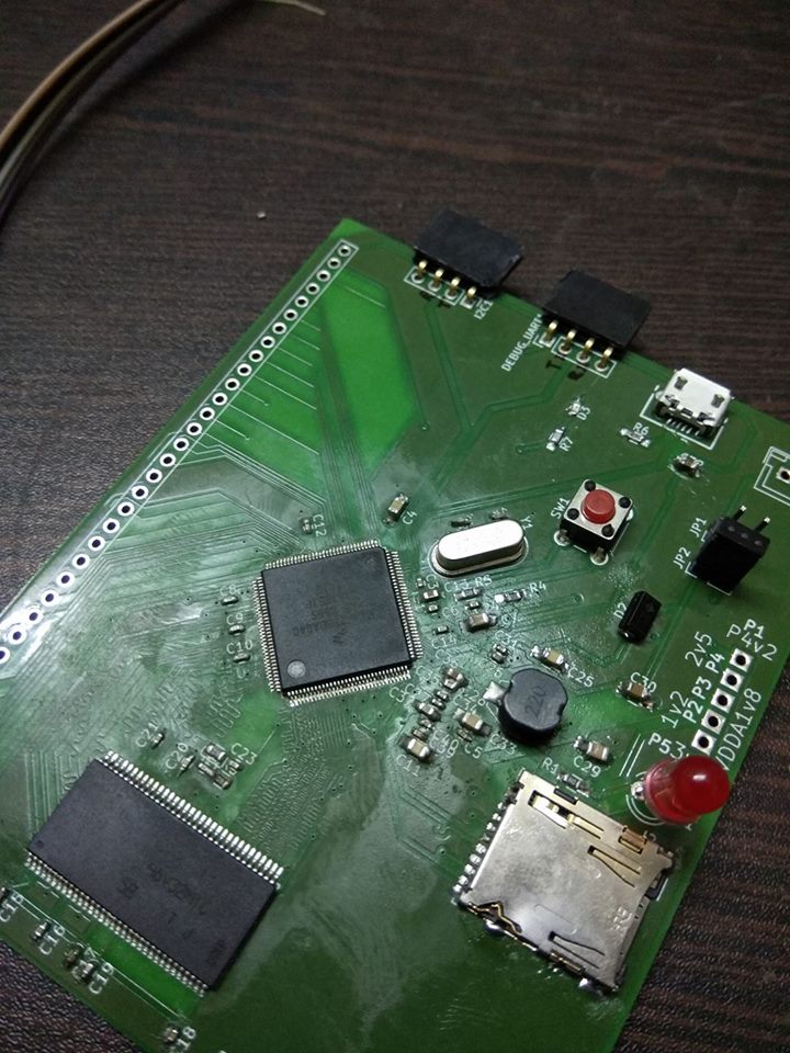
I also ordered components. I didn't realize this would be a pain. element14 is not that accessible for an individual. I ordered mostly from Shelfkey and some from KitsNSpares. I am still tensed if footprints I chose will match the actual components. Second I am very much tensed about soldering 0402 components.
Final version of PCB sent for fab in pcbpower.
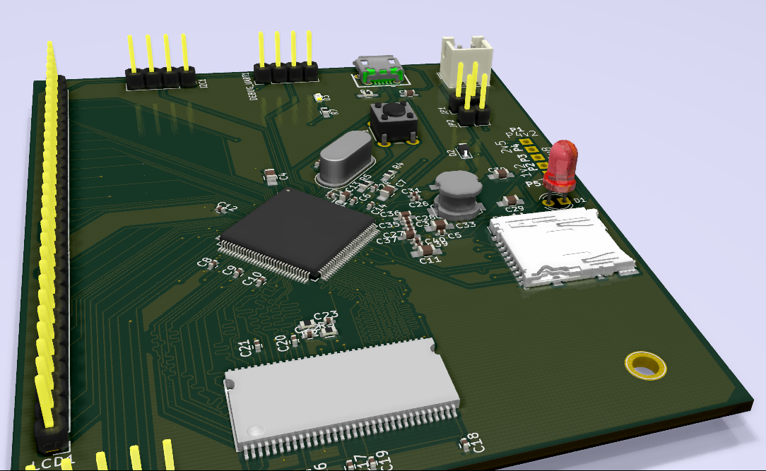
Added few options to use DCDC. I was not comfortable of grounding DCDC_BATT and BATT pins, so I added a few jumpers. Also added provisions to add battery.
Learnt basic Freecad to build the Step files of DDR SDRAM 66TSOP. Here is the project I created - MT46V32M16P-5B-Freecad-Step.
Initial version. DDR RAM child 3D missing and SD card's 3D missing.
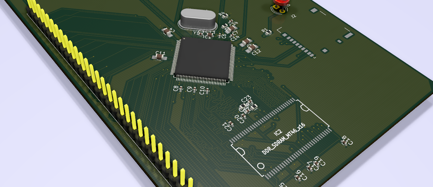
Learnt Length Matching in Kicad.
Figured out placement of components. I am going with Clementine Core's placement which seems very good.
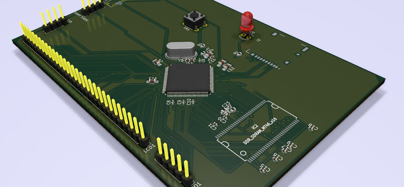
| Qty | Value | Footprint | References |
|---|---|---|---|
| 21 | 100n | Capacitors_SMD:C_0402 | C3, C10, C12, C14, C15, C16, C17, C18, C19, C20, C21, C22, C23, C24, C31, C33 +5 |
| 6 | 47k | Resistors_SMD:R_0603_HandSoldering | R9, R10, R11, R12, R13, R14 |
| 4 | 1u | Capacitors_SMD:C_0603_HandSoldering | C13, C36, C37, C41 |
| 4 | 22u | Capacitors_SMD:C_0805_HandSoldering | C4, C5, C11, C25 |
| 3 | 0.1ohm | Resistors_SMD:R_0603_HandSoldering | R19, R25, R26 |
| 3 | 100k | Resistors_SMD:R_0603_HandSoldering | R21, R22, R23 |
| 3 | 10n | Capacitors_SMD:C_0402 | C28, C34, C40 |
| 3 | 5.1v | Diodes_SMD:D_SOD-323_HandSoldering | D4, D5, D10 |
| 2 | 10p | Capacitors_SMD:C_0402 | C1, C2 |
| 2 | 1K | Resistors_SMD:R_0603 | R15, R16 |
| 2 | 1K1% | Resistors_SMD:R_0603 | R2, R3 |
| 2 | 1k | Resistors_SMD:R_0603_HandSoldering | R1, R7 |
| 2 | 1u | Capacitors_SMD:C_0402 | C26, C27 |
| 2 | 4.7k | Resistors_SMD:R_0603_HandSoldering | R6, R8 |
| 2 | 47K | Resistors_SMD:R_0603 | R17, R18 |
| 2 | 47u | Capacitors_SMD:C_0805_HandSoldering | C29, C30 |
| 2 | 5.1v | Diodes_THT:D_DO-35_SOD27_P7.62mm_Horizontal | D7, D9 |
| 2 | CONN_01X04 | Pin_Headers:Pin_Header_Straight_1x04_Pitch2.54mm | DEBUG_UART1, I2C1 |
| 1 | 100K | Resistors_SMD:R_0603_HandSoldering | R4 |
| 1 | 10k | Resistors_SMD:R_0603_HandSoldering | R24 |
| 1 | 10uF | Capacitors_THT:CP_Radial_D5.0mm_P2.50mm | C38 |
| 1 | 120R | Resistors_SMD:R_0603 | R27 |
| 1 | 1K | Resistors_SMD:R_0603_HandSoldering | R5 |
| 1 | 1u | Capacitors_SMD:C_0805_HandSoldering | C7 |
| 1 | 1v | iMX233-OLinuXino-NANO_Rev_BEagle:GOGO_TESTPAD2 | P6 |
| 1 | 1v2 | iMX233-OLinuXino-NANO_Rev_BEagle:GOGO_TESTPAD2 | P2 |
| 1 | 22uF | Capacitors_THT:CP_Radial_D5.0mm_P2.50mm | C42 |
| 1 | 22uH | mylib:Bourns22uh6x6mm | L1 |
| 1 | 24Mhz | Crystals:Crystal_HC49-4H_Vertical | Y1 |
| 1 | 2v5 | iMX233-OLinuXino-NANO_Rev_BEagle:GOGO_TESTPAD2 | P4 |
| 1 | 3.3v | Diodes_SMD:D_SOD-123 | D6 |
| 1 | 3.3v | Diodes_THT:D_DO-35_SOD27_P7.62mm_Horizontal | D8 |
| 1 | 3v3 | iMX233-OLinuXino-NANO_Rev_BEagle:GOGO_TESTPAD2 | P5 |
| 1 | 4.7uf | Capacitors_SMD:C_0603_HandSoldering | C32 |
| 1 | 470k | Resistors_SMD:R_0603_HandSoldering | R20 |
| 1 | 4p2 | iMX233-OLinuXino-NANO_Rev_BEagle:GOGO_TESTPAD2 | P1 |
| 1 | Battery | Connectors_JST:JST_XH_B02B-XH-A_02x2.50mm_Straight | BT1 |
| 1 | CONN_01X01 | Connectors:1pin | J2 |
| 1 | CONN_01X05 | Pin_Headers:Pin_Header_Straight_1x05_Pitch2.54mm | GPIO1 |
| 1 | CONN_01X30 | Pin_Headers:Pin_Header_Straight_1x30_Pitch2.54mm | LCD1 |
| 1 | DDR_SDRAM_MT46_x16 | mylib:TSOP66_JEDEC_DDR_SDRAM | IC2 |
| 1 | D_Batt | Diodes_SMD:D_SOD-323_HandSoldering | D2 |
| 1 | LED | LEDs:LED_0603 | D3 |
| 1 | LED | LEDs:LED_D4.0mm | D1 |
| 1 | SD_ebay-uSD-push/push_SMD | mylib:uSDcard | XS1 |
| 1 | SWITCH_PUSHBUTTON | Buttons_Switches_THT:SW_PUSH_6mm | SW1 |
| 1 | USB_OTG | mylib:USB_Micro-B_MOLEX_105017-0001 | J1 |
| 1 | USB_boot | Pin_Headers:Pin_Header_Straight_1x02_Pitch2.54mm | JP_USB_boot1 |
| 1 | VDDA1v8 | iMX233-OLinuXino-NANO_Rev_BEagle:GOGO_TESTPAD2 | P3 |
| 1 | WithBatt | Pin_Headers:Pin_Header_Straight_1x02_Pitch2.54mm | JP1 |
| 1 | WithoutBatt | Pin_Headers:Pin_Header_Straight_1x02_Pitch2.54mm | JP2 |
| 1 | iMX233 | mylib:LQFP-128_14x14mm_Pitch0.4mm | IC1 |
It measures 74.1 × 92 mm and has 2 copper layers, 1.6 mm thick.
101 parts. The full list of its parts is on this page, with links to each part's symbol and footprint where PCBKit's library has them.
From the samarjit/MyIMX233 repository on GitHub, at the commit this page was made from: the board is MyIMX233.kicad_pcb. PCBKit opens the board in the browser, with nothing to install.
Its repository states no licence, so its author keeps all rights: ask samarjit before reusing the design.
sudomesh/disaster-radio
A (paused) work-in-progress long-range, low-bandwidth wireless disaster recovery mesh network powered by the sun.


cnlohr/cnhardware
My dumping grounds for all my kicad projects and random hardware bringup.

aeberbach/A1200KB
As of right now this is revision 4. I know it could be improved very, very slightly by changing the position of key groups by less than a millimetre but I think it's complete now.

profdc9/ModularTuner
A Modular Antenna Tuner for a Phased Array Antenna System

ceoloide/corney-island
An Ergogen-based, autogenerated version of foostan's crkbd (Corne) split keyboard