

2 layers120 × 80 mm
Biometric scanner
Sid93/levram-biometric-attendance-scanner
ESP32-S3 face-recognition factory attendance terminal — firmware, KiCad PCB, OpenSCAD enclosure, BOM
45 parts1

 salvogendut/reverseMX4
An extension board for the Amstrad CPC which uses edge connectors instead of IDC ones
ReverseMX4 is an open-source printed circuit board by salvogendut, from the salvogendut/reverseMX4 repository on GitHub. It is a 4-layer board of 100 × 200 mm with 10 parts on 52 nets, routed with 366 tracks and 48 vias.
It is built around the 100UF 10V. Its parts include 6 connectors, 2 capacitors and 1 fuse.
This project is a four-slot expansion backplane for the Amstrad CPC bus. A short cable connects the computer to a 50-contact male edge tongue on the backplane. Four vertical, 50-contact female card-edge sockets accept expansion cards that have the classic CPC edge finger pattern. There are no MX4/IDC headers on the backplane.
docs/cpc-expansion-pinout.csv; do not rely on the shell orientation or ribbon stripe alone.The classic CPC expansion port has 25 contacts on each face, 2.54 mm pitch and 1.6 mm nominal card thickness. The Plus uses a 50-contact Delta style connector with the same bus signals. The board does not translate logic or select slots; all four sockets share the expansion bus in parallel. Expansion cards must themselves handle address decoding and bus arbitration. Simultaneous use also depends on the computer's available power and the attached cards' electrical loading.
reverseMX4.kicad_sch, reverseMX4.kicad_pcb and reverseMX4.kicad_pro are the editable KiCad 10 project.JP1 selects CPC power (pins 1–2) or external regulated 5 V (pins 2–3). The external input passes through a 3 A hold PTC fuse. The sources are isolated from each other by the removed position of the shunt.docs/assembly.md covers cable checks, part placement and manufacturing notes. docs/bom.csv lists parts. docs/preview/schematic.pdf and docs/preview/top-assembly.svg are review views.fab/reverseMX4-A0-gerbers.zip contains the four copper layers, masks, silkscreens, outline and separate plated/non-plated drill files. Read fab/README.md before ordering.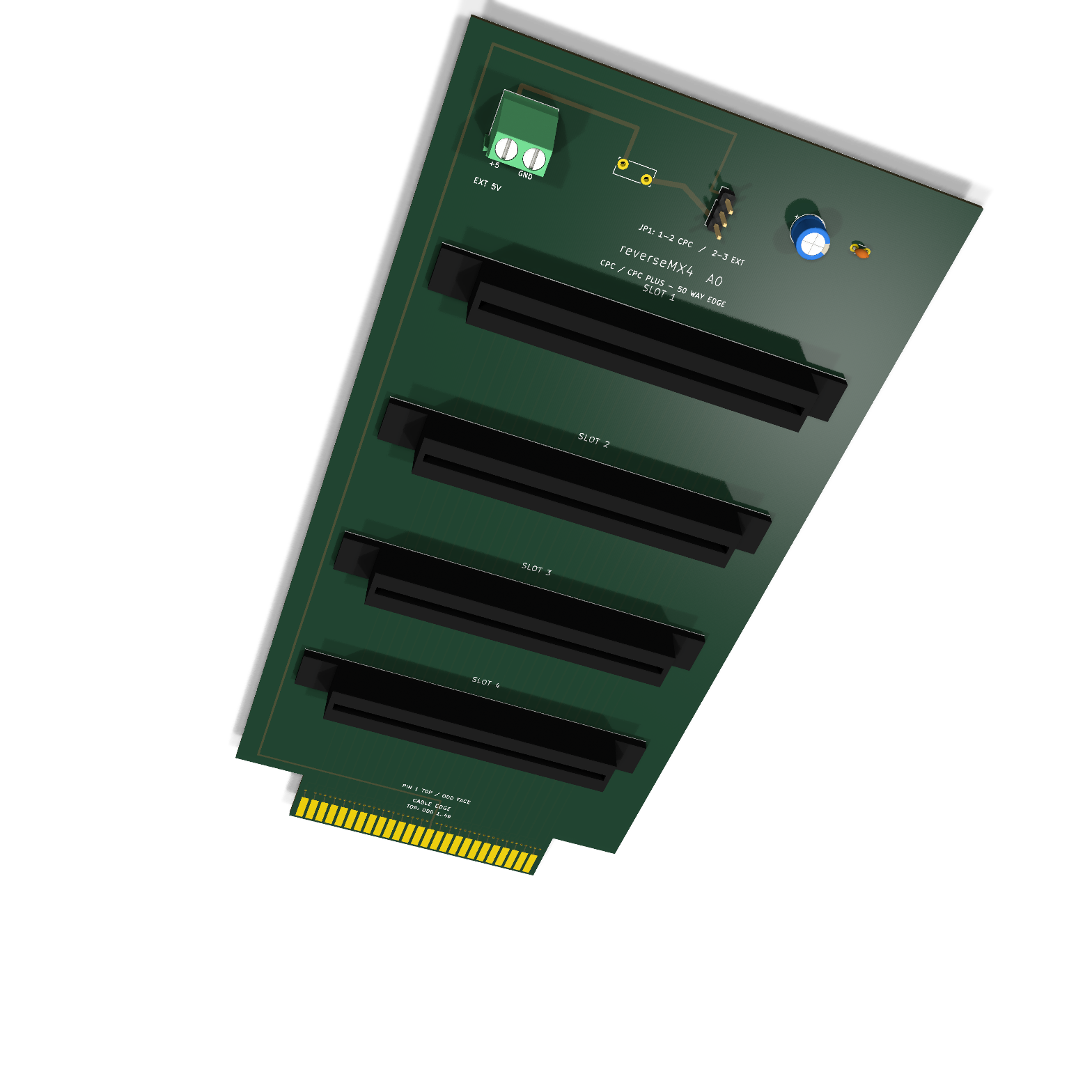
Open the full-size 3D rendering. The four socket bodies use a simple local preview model to show position and card openings; their exact housing shape and height have not been verified against a physical EDAC part.
KiCad ERC and DRC pass with zero violations, zero unrouted items and zero schematic parity issues. The PCB is an untested prototype: connector mating, card clearance, cable orientation and operation on real CPC/CPC Plus computers still need physical verification before a production run.
The reference URL supplied for this project, rabs664/Amstrad-CPC-Plus-Expansion-Backplane, was unavailable during the initial research. Its layout has not been copied. The pin map below comes from Amstrad's CPC 464 manual and Arnold V CPC Plus expansion specification.
| Qty | Value | Footprint | References |
|---|---|---|---|
| 1 | 100nF_50V | Capacitor_THT:C_Disc_D3.0mm_W1.6mm_P2.50mm | C2 |
| 1 | 100uF_10V | Capacitor_THT:CP_Radial_D6.3mm_P2.50mm | C1 |
| 1 | 3A_PTC | Fuse:Fuse_Bourns_MF-RG300 | F1 |
| 1 | 5V_SOURCE_SELECT | Connector_PinHeader_2.54mm:PinHeader_1x03_P2.54mm_Vertical | JP1 |
| 1 | CPC_CABLE_EDGE | reverseMX4:CPC_Edge_2x25 | J1 |
| 1 | EDGE_SLOT_1 | reverseMX4:EDAC_395-050-521-204 | J2 |
| 1 | EDGE_SLOT_2 | reverseMX4:EDAC_395-050-521-204 | J3 |
| 1 | EDGE_SLOT_3 | reverseMX4:EDAC_395-050-521-204 | J4 |
| 1 | EDGE_SLOT_4 | reverseMX4:EDAC_395-050-521-204 | J5 |
| 1 | EXT_5V_IN | TerminalBlock_Phoenix:TerminalBlock_Phoenix_MKDS-1,5-2_1x02_P5.00mm_Horizontal | J6 |
It measures 100 × 200 mm and has 4 copper layers, 1.6 mm thick.
10 parts, built around the 100UF 10V. The full list of its parts is on this page, with links to each part's symbol and footprint where PCBKit's library has them.
From the salvogendut/reverseMX4 repository on GitHub, at the commit this page was made from: the board is reverseMX4.kicad_pcb and its schematic reverseMX4.kicad_sch. PCBKit opens the board in the browser, with nothing to install.
Its repository states no licence, so its author keeps all rights: ask salvogendut before reusing the design.
Sid93/levram-biometric-attendance-scanner
ESP32-S3 face-recognition factory attendance terminal — firmware, KiCad PCB, OpenSCAD enclosure, BOM

xxdamlaxx/DroidVR
A DIY VR controller ecosystem — open-source hardware and firmware for SteamVR-compatible motion controllers.

8aChristian/InduLink-485
The board follows rigorous IPC (IPC-2152, IPC-2221, IPC-7351) standards, complete with galvanic isolation, industrial transient protection (TVS, Schottky, PTC Polyfuse), a wide-input step-down switching power…

Abdullah-Atif/gsm-gps-tracker
Live vehicle tracker: ESP32 / ESP32-C3 + NEO-M8N GPS + SIM800L (2G) -> MQTT -> live web map. Firmware, KiCad PCBs, wiring diagram.

pavan-firmware/EH-Master-Repo
This directory contains the KiCad Schematic and PCB Design Project for the EH Smart Switch (3X / 4X Channel with BL0942 Metering).

purpletue/TinyLilFella
An absolutely microscopic (metaphorically) microcontroller board based on an STM32C071. The name is fully deserved.

