2 layers20.5 × 24.8 mm
 sajattack/yo653016
FPGA Gateware for Commodore MOS 6530 RRIOT
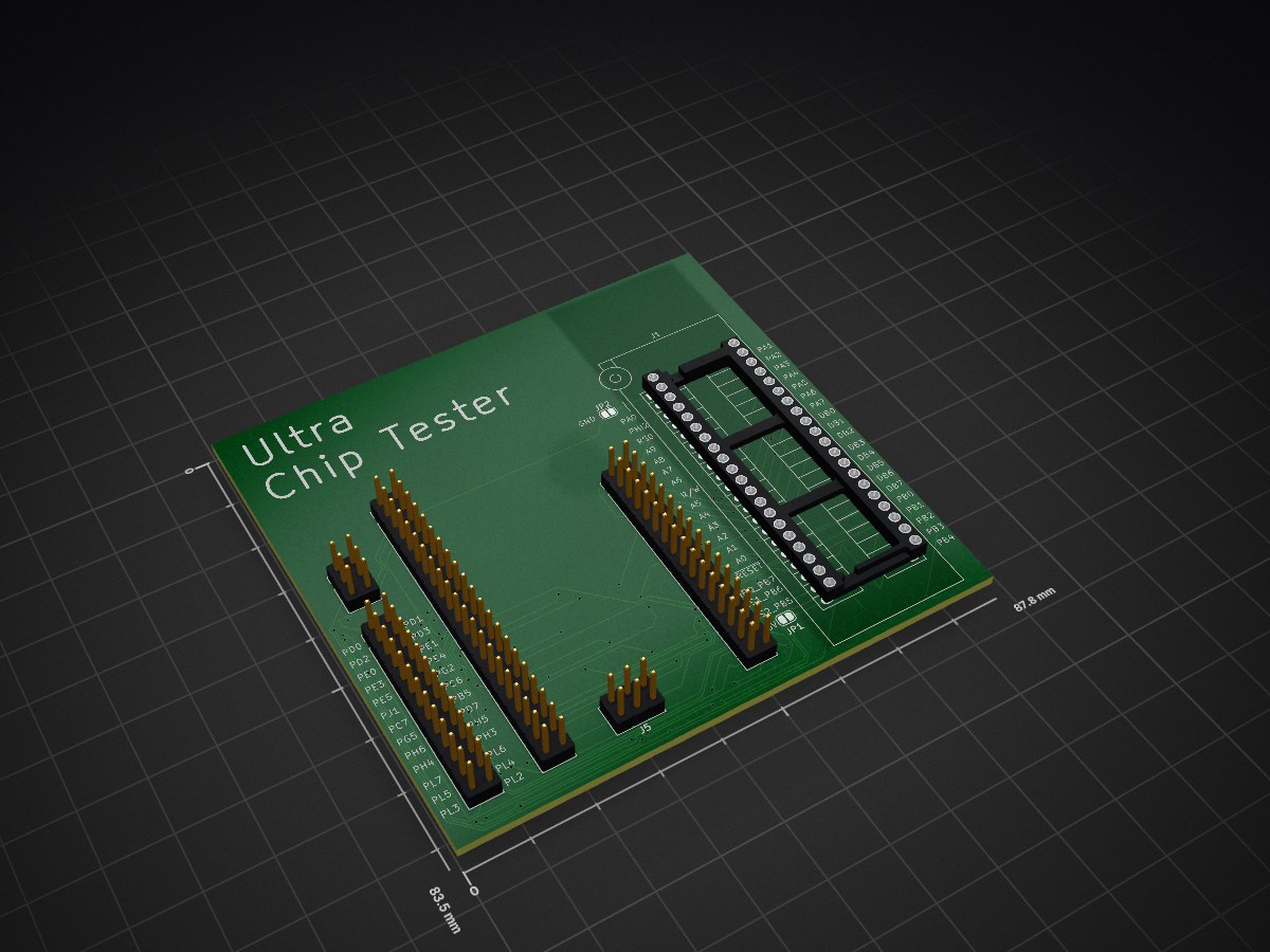
Chip tester is an open-source printed circuit board by sajattack, from the sajattack/yo6530 repository on GitHub, published under the MIT licence. It is a 2-layer board of 87.8 × 83.5 mm with 8 parts on 75 nets, routed with 958 tracks and 97 vias.
It belongs with the fPGA and programmable logic and retro computing and games boards and the FPGA and CPLD boards of this library.
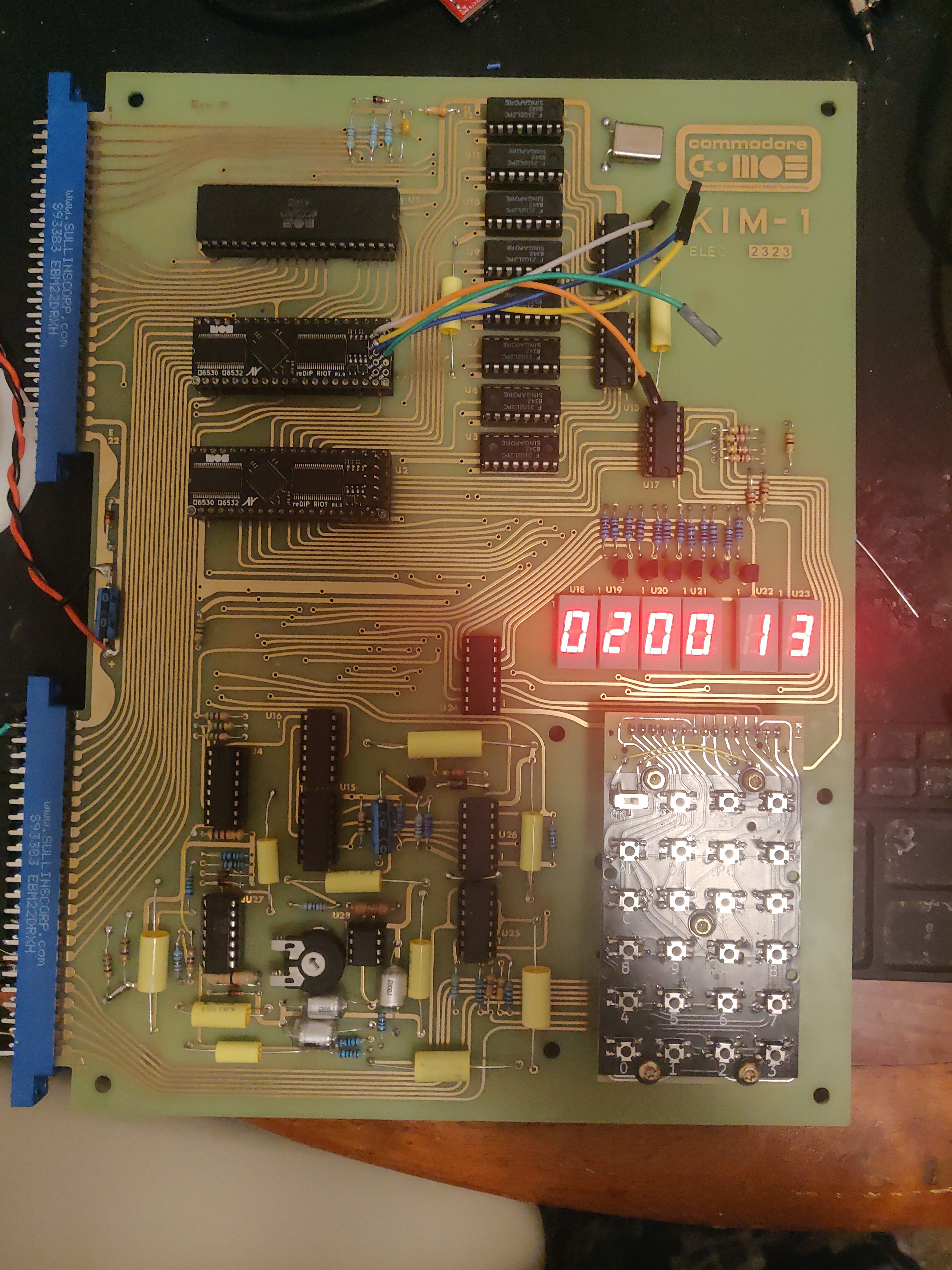

https://github.com/daglem/redip-riot
| Raspi pin name/num | ReDIP RIOT name/num |
|---|---|
| SCK / 23 | SPI_SCLK / 3 |
| MISO / 21 | SPI_SIO1 / 5 |
| MOSI / 19 | SPI_SIO0 / 7 |
| CE0 / 24 | SPI_CS / 1 |
| GPIO25 / 22 | CDONE / 2 |
| 3v3 / 17 | 3v3 / 8 |
| GND / 20 | GND / 6 |
| GPIO24 / 18 | CRESET / 4 |
make MCS6530_002=1 # build the project
scp build/mcs6530.bin pi@<your-pi's-ip>: # copy the build artifact to the pi for flashing
ssh pi@<your-pi's-ip> # connect to the pi
sudo raspi-config # go into the interfaces menu and enable spi after running this command
pinctrl set 24 op dl # put the board into programming mode by setting creset low
flashrom -p linux_spi:dev=/dev/spidev0.0,spispeed=20000 # if this detects the device, all is good, otherwise check your spi is enabled and your wiring
truncate -s 128K mcs6530.bin # pad the rom to 128K
flashrom -p linux_spi:dev=/dev/spidev0.0,spispeed=20000 -w mcs6530.bin # write the flash
pinctrl set 24 ip pu # exit programming mode by returning creset to input pullupmake MCS6530_002=1 sim
./obj_dir/Vverilator_top # this will throw assertion errors if the tests failAlso you can examine the logic signals output during the test in the Vverilator_top.vcd file using GTKWave
| Qty | Value | Footprint | References |
|---|---|---|---|
| 2 | Conn_02x03_Odd_Even | Connector_PinHeader_2.54mm:PinHeader_2x03_P2.54mm_Vertical | J4, J5 |
| 2 | Jumper_2_Bridged | Jumper:SolderJumper-2_P1.3mm_Bridged_RoundedPad1.0x1.5mm | JP1, JP2 |
| 1 | Conn_02x12_Counter_Clockwise | Connector_PinHeader_2.54mm:PinHeader_2x13_P2.54mm_Vertical | J6 |
| 1 | Conn_02x16_Odd_Even | Connector_PinHeader_2.54mm:PinHeader_2x16_P2.54mm_Vertical | J3 |
| 1 | Conn_02x20_Counter_Clockwise | Socket:3M_Textool_240-1288-00-0602J_2x20_P2.54mm | J1 |
| 1 | Conn_02x21_Odd_Even | Connector_PinHeader_2.54mm:PinHeader_2x21_P2.54mm_Vertical | J2 |
It measures 87.8 × 83.5 mm and has 2 copper layers, 1.6 mm thick.
8 parts. The full list of its parts is on this page, with links to each part's symbol and footprint where PCBKit's library has them.
From the sajattack/yo6530 repository on GitHub, at the commit this page was made from: the board is hw_tester/mega2560_pro/hw/kicad/chip_tester.kicad_pcb and its schematic hw_tester/mega2560_pro/hw/kicad/chip_tester.kicad_sch. PCBKit opens the board in the browser, with nothing to install.
Its repository publishes it under the MIT licence: you may reuse it on that licence's terms (keep the author's notice, and for a copyleft licence share your changes alike).

joeycastillo/Sensor-Watch
A board replacement for the classic Casio F-91W wristwatch

rusefi/rusefi
rusefi - GPL internal combustion engine control unit

hoglet67/RGBtoHDMI
Bare-metal Raspberry Pi project that provides pixel-perfect sampling of Retro Computer RGB/YUV video and conversion to HDMI

shanteacontrols/OpenDeck
A platform for building interactive control and sensing devices using MIDI and OSC built with Zephyr RTOS.

hackclub/OnBoard
💡 Join 1,000 teenagers and make your first PCB with a $100 grant!

dangiu/PicoMemcard
Emulating PSX Memory Card (or controller) using a Raspberry Pi Pico

OLIMEX/DIY-LAPTOP
Do It Yourself Open Source Hardware and Software Modular Hacker's Friendly Laptop