
4 layers90 × 90 mm
Power distribution
menloresearch/asimov-1
v1 of Asimov, an open-source humanoid robot
25 parts1.4kCERN-OHL-S-2.0

 s-light/LEDBoard_4x4_HD1
PCBs for magic amulet
LEDBoard 4x4 HD is an open-source printed circuit board by s-light, from the s-light/LEDBoard_4x4_HD repository on GitHub, published under the MIT licence. It is a 4-layer board of 33 × 13.6 mm with 25 parts on 57 nets, routed with 874 tracks and 120 vias.
It is built around the TLC5957RTQ. Its parts include 4 capacitors, 3 connectors, 1 resistor and 1 IC.
PCB originally designed for magic_amulet,
but now used in magic_crystal
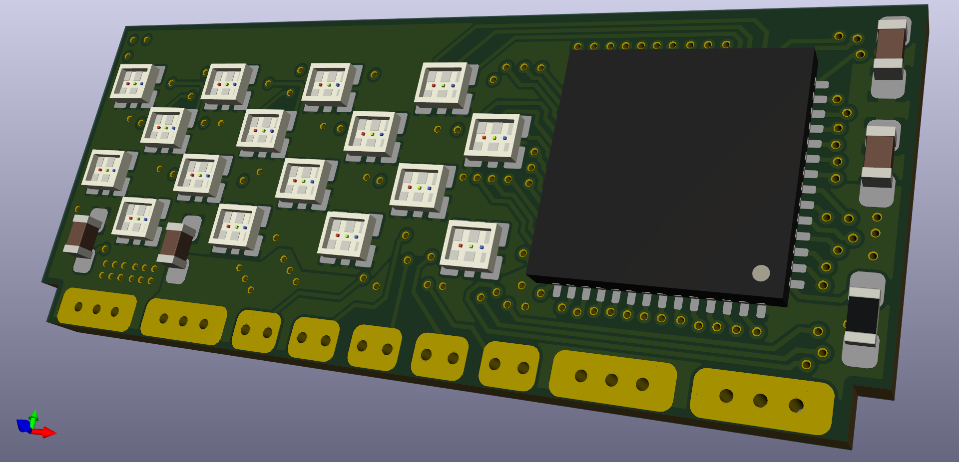
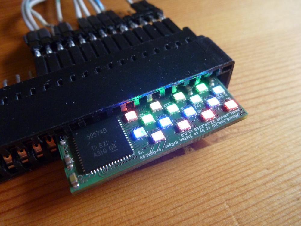
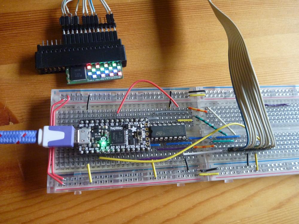
Overall Size:
33mm x 14mm
4layer board - uses 150mil traces and 100mil trace spacing
shown pcb came from aisler
LED-Driver: TLC5957 (48ch CC 9-16Bit-PWM driver)
more information in AppNote Build a High-Density, High-Refresh Rate, Multiplexing Panel With the TLC5957
LED: Rohm MSL0402RGBU (1.8x1.6x0.5mm RGB)
can be ordered with aisler parts-package
or also with this list at mouser
or with plain part numbers:
Qty.    Mfr. No             Manufacturer            Description
16      MSL0402RGBU1        ROHM Semiconductor      Standard LEDs - SMD RGB 624/527/470nm 5V 400/550/180mcd 30mA
1       TLC5957RTQR         Texas Instruments       LED Lighting Drivers 48-channel, 16bit ES PWM LED driver
2       GRM188R61A226ME15D  Murata                  Multilayer Ceramic Capacitors MLCC - SMD/SMT 0603 22uF 10volts *Derate Voltage/Temp
2       GCM188R91E104KA37D  Murata                  Multilayer Ceramic Capacitors MLCC - SMD/SMT 0603 0.1uF 25volts X8R 10%
1 ERJ-PB3B7501V Panasonic Thick Film Resistors - SMD 0603 Anti-Surge Res. 0.1%, 7.5Kohmif you want to drive the leds with full power (up to 25mA/color)
you definitely need a heatsink.
the pcb backside get to >= 60°C very fast without a heatsink!
also remember that one board needs up to 1.2A@5V = 6W
RIREF(kΩ) = VIREF(V) / IOLCMax(mA)× Gain  | / Gain
RIREF(kΩ) / Gain = VIREF(V) / IOLCMax(mA)  | swap
Gain / RIREF(kΩ) = IOLCMax(mA) / VIREF(V)  | x VIREF(V)
Gain / RIREF(kΩ) x VIREF(V) = IOLCMax(mA)

Gain / 7.4kΩ x 1.2V = IOLCMax(mA)| Gain | BC | IOLCMax |
|---|---|---|
| 20.0 | 0x0 | 3.2mA |
| 39.5 | 0x1 | 6.4mA |
| 58.6 | 0x2 | 9.5mA |
| 80.9 | 0x3 | 13.1mA |
| 100.0 | 0x4 | 16.2mA |
| 113.3 | 0x5 | 18.4mA |
| 141.6 | 0x6 | 23.0mA |
| 154.5 | 0x7 | 25.0mA |
| Qty | Value | Footprint | References |
|---|---|---|---|
| 16 | LED_RGB | LEDs_SMD_NICHIA:LED_RGB_0706_1816Metric_ROHM_ThermalVias | D_0x0, D_0x1, D_0x2, D_0x3, D_1x0, D_1x1, D_1x2, D_1x3, D_2x0, D_2x1, D_2x2, D_2x3, D_3x0, D_3x1, D_3x2, D_3x3 |
| 2 | 0.1uF | Capacitor_SMD:C_0603_1608Metric_Pad1.05x0.95mm_HandSolder | C2, C3 |
| 2 | 47uF 6.3V | Capacitor_SMD:C_0603_1608Metric_Pad1.05x0.95mm_HandSolder | C1, C4 |
| 2 | power | PCB_SolderMount:Conn_01x02_SMD_90deg_SolderMount | J1, J3 |
| 1 | 7.5KOhm 0.1% | Resistor_SMD:R_0603_1608Metric_Pad1.05x0.95mm_HandSolder | R1 |
| 1 | TLC5957 | Package_DFN_QFN:QFN-56-1EP_8x8mm_P0.5mm_EP5.6x5.6mm_ThermalVias | U1 |
| 1 | data | PCB_SolderMount:Conn_01x05_SMD_90deg_SolderMount | J2 |
menloresearch/asimov-1
v1 of Asimov, an open-source humanoid robot

opentac/opentac
OpenTac: open tools to design, fabricate, read and simulate flex-PCB tactile skins that sense normal and shear force, for any robot surface.

ManiacalLabs/AllPixel
Firmware and Board Designs for the AllPixel LED Controller Board: Please direct questions and support requests to https://forum.maniacallabs.com/c/hardware - The Issues list here should be reserved for actual bugs.


kounocom/Mumo
A compact 13×18mm IMU module featuring the TDK InvenSense ICM-45686 6-axis IMU with integrated 32.768kHz clock and QST QMC6309H 3-axis magnetometer.


It measures 33 × 13.6 mm and has 4 copper layers, 1.6 mm thick.
25 parts, built around the TLC5957RTQ. The full list of its parts is on this page, with links to each part's symbol and footprint where PCBKit's library has them.
From the s-light/LEDBoard_4x4_HD repository on GitHub, at the commit this page was made from: the board is LEDBoard_4x4_HD.kicad_pcb. PCBKit opens the board in the browser, with nothing to install.
Its repository publishes it under the MIT licence: you may reuse it on that licence's terms (keep the author's notice, and for a copyleft licence share your changes alike).