
2 layers231.1 × 106.7 mm

 ryu10/usbkbdshield_vt1006
USB Keyboard Shield for VT100
Usbkbd vt100 is an open-source printed circuit board by ryu10, from the ryu10/usbkbdshield_vt100 repository on GitHub. It is a 2-layer board of 68.6 × 53.2 mm with 30 parts on 50 nets, routed with 327 tracks and 7 vias.
It is built around the LM393. Its parts include 18 resistors, 4 ICs, 2 capacitors and 2 connectors. It belongs with the keyboards and input boards of this library.
Rev. 2.1
This shield connects a standard USB keyboard to the DEC VT100 terminal.
The Gerber file, BOM, schematics and Arduino sketch for the shield are included in this repo. For the steps to assemble, program and connect the shields, please see the sections below.
Note: this shield uses the USB Host Shield from Circuits@Home.
Please use the information in this repo at your own risk. No warranty or guarantee is provided.
The details of each step are described in the next few sections.
The USB Keyboard Shield for VT100 can be assembled using the following info:
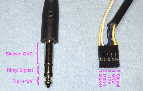
To make the keyboard cable, connect these components:
PIN CONNECTIONS
| Pin | Plug | Value |
|---|---|---|
| 1* | - | (spk+)* |
| 2* | - | (spk-)* |
| 3 | Tip | +12V |
| 4 | Sleeve | GND |
| 5 | Ring | Signal |
* optional
The pin connector is attached to J1 header on the USB Keyboard shield for VT100. The stereo plug is connected to the keyboard port on VT100 terminal.
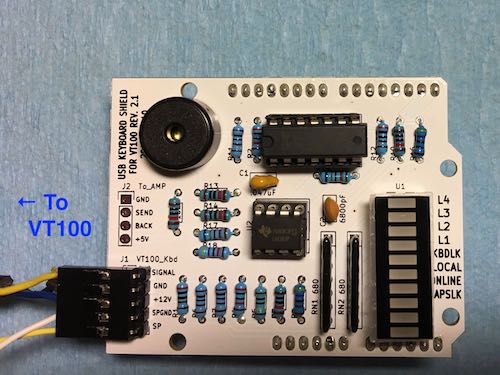
It is recommended to program the Arduino Uno before attaching the shields.
Install USB Host Shield Library 2.0 and Timer1 Library into Arduino IDE.
Clone or download this project.
Open the sketch usbkeyboardvt100/usbkeyboardvt100.ino in Arduino IDE, and program the Arduino Uno.
There are two options in usbkeyboardvt100.ino:
// SWAPCAPS: If defined, LeftCtrl and CapsLock are swapped on USB Keyboard.
#define SWAPCAPS

// SWAPLFBAR: If defined, swap LineFeed and '|\' key codes for VT100.
//#define SWAPLFBAR
Comment out/uncomment the #define lines as needed.
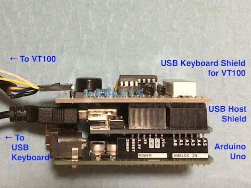
Some hard-to-guess keys:
| VT100 Key | USB Keyboard Key |
|---|---|
| SET UP | F1, SysRq |
| CTRL | Caps Lock |
| CAPS LOCK | Left Ctrl |
| BREAK | Break |
| LINE FEED | End |
| NO SCROLL | Scroll Lock |
| PF1 | Num Lock, F9 |
| PF2 | (numpad) /, F10 |
| PF3 | (numpad) *, F11 |
| PF4 | Page Up, F12 |
| (numpad) , | (numpad) + |
The key mappings are defined in usb_key_tbl[] in usbkeyboardvt100.h. Also see "Configuration Options" above.
The following configuration was used during development of this shield:
The code is released under the GNU General Public License.
| Qty | Value | Footprint | References |
|---|---|---|---|
| 5 | 10k | Resistors_THT:R_Axial_DIN0204_L3.6mm_D1.6mm_P7.62mm_Horizontal | R3, R9, R10, R13, R14 |
| 3 | 1k | Resistors_THT:R_Axial_DIN0204_L3.6mm_D1.6mm_P7.62mm_Horizontal | R6, R7, R11 |
| 2 | 20k | Resistors_THT:R_Axial_DIN0204_L3.6mm_D1.6mm_P7.62mm_Horizontal | R2, R4 |
| 2 | 2k | Resistors_THT:R_Axial_DIN0204_L3.6mm_D1.6mm_P7.62mm_Horizontal | R1, R12 |
| 2 | 4k7 | Resistors_THT:R_Axial_DIN0204_L3.6mm_D1.6mm_P7.62mm_Horizontal | R8, R16 |
| 2 | 680 | Resistors_THT:R_Array_SIP7 | RN1, RN2 |
| 2 | 68k | Resistors_THT:R_Axial_DIN0204_L3.6mm_D1.6mm_P7.62mm_Horizontal | R15, R17 |
| 1 | usbkbd_vt100:Diode_symbol | ||
| 1 | .047uF | Capacitors_THT:C_Disc_D5.0mm_W2.5mm_P2.50mm | C1 |
| 1 | 1M | Resistors_THT:R_Axial_DIN0204_L3.6mm_D1.6mm_P7.62mm_Horizontal | R5 |
| 1 | 47k | Resistors_THT:R_Axial_DIN0204_L3.6mm_D1.6mm_P7.62mm_Horizontal | R18 |
| 1 | 6800pF | Capacitors_THT:C_Disc_D5.0mm_W2.5mm_P2.50mm | C2 |
| 1 | 74LS06N | Housings_DIP:DIP-14_W7.62mm_Socket | U3 |
| 1 | ARDUINO_FOOTPRINT | usbkbd_vt100:ARDUINO_SHIELD_NOICSP | SHIELD1 |
| 1 | BUZZER | Buzzers_Beepers:Buzzer_12x9.5RM7.6 | U4 |
| 1 | LED10ARRAY | Housings_DIP:DIP-20_W7.62mm | U1 |
| 1 | LM393 | Housings_DIP:DIP-8_W7.62mm_Socket | U2 |
| 1 | To_AMP | Pin_Headers:Pin_Header_Straight_1x04 | J2 |
| 1 | VT100_Kbd | Pin_Headers:Pin_Header_Angled_1x05 | J1 |
It measures 68.6 × 53.2 mm and has 2 copper layers, 1.6 mm thick.
30 parts, built around the LM393. The full list of its parts is on this page, with links to each part's symbol and footprint where PCBKit's library has them.
From the ryu10/usbkbdshield_vt100 repository on GitHub, at the commit this page was made from: the board is usbkbd_vt100_KiCad/usbkbd_vt100.kicad_pcb. PCBKit opens the board in the browser, with nothing to install.
Its repository states no licence, so its author keeps all rights: ask ryu10 before reusing the design.


schlae/snark-barker-mca
A Sound Blaster compatible sound card for Micro Channel bus computers

michaelruppe/FSAE
Projects for Formula SAE Electric Vehicle competition (Australia 2019/2020)

AllYarnsAreBeautiful/ayab-hardware
Contains the schematics and layouts for the AYAB Arduino shield

17o2/bluetooth-minidisc
Adding built-in bluetooth connectivity to a 20-year-old Mindisc player

bluepylons/USB-C-3-way-splitter
A splitter board (for making a cable splitter) for turning a 5V 3A USB power source to 3 5V 1A USB sources