2 layers116.8 × 30 mm
Type d
google/mozc-devices
Circuit diagrams and firmware source code for Gboard DIY keyboards
14 parts3kApache-2.0

 ryu10/emu68022
HEX ファイル emu6802.X.production.hex を PIC へ書き込みます(PIC18F47Q84 用です)。ソースコードは emu6802.X 以下を参照してください。プロジェクトは MPLAB X IDE で開きます。
Emu6802 is an open-source printed circuit board by ryu10, from the ryu10/emu6802 repository on GitHub. It is a 2-layer board of 37 × 75 mm with 14 parts on 46 nets, routed with 467 tracks and 13 vias.
Its parts include 5 connectors, 2 capacitors and 1 IC.
[v0.6]
(日本語 | EN)
電脳伝説様作の EMUZ80 を利用した PIC16F47Q84 + MC6802 コンピュータです。
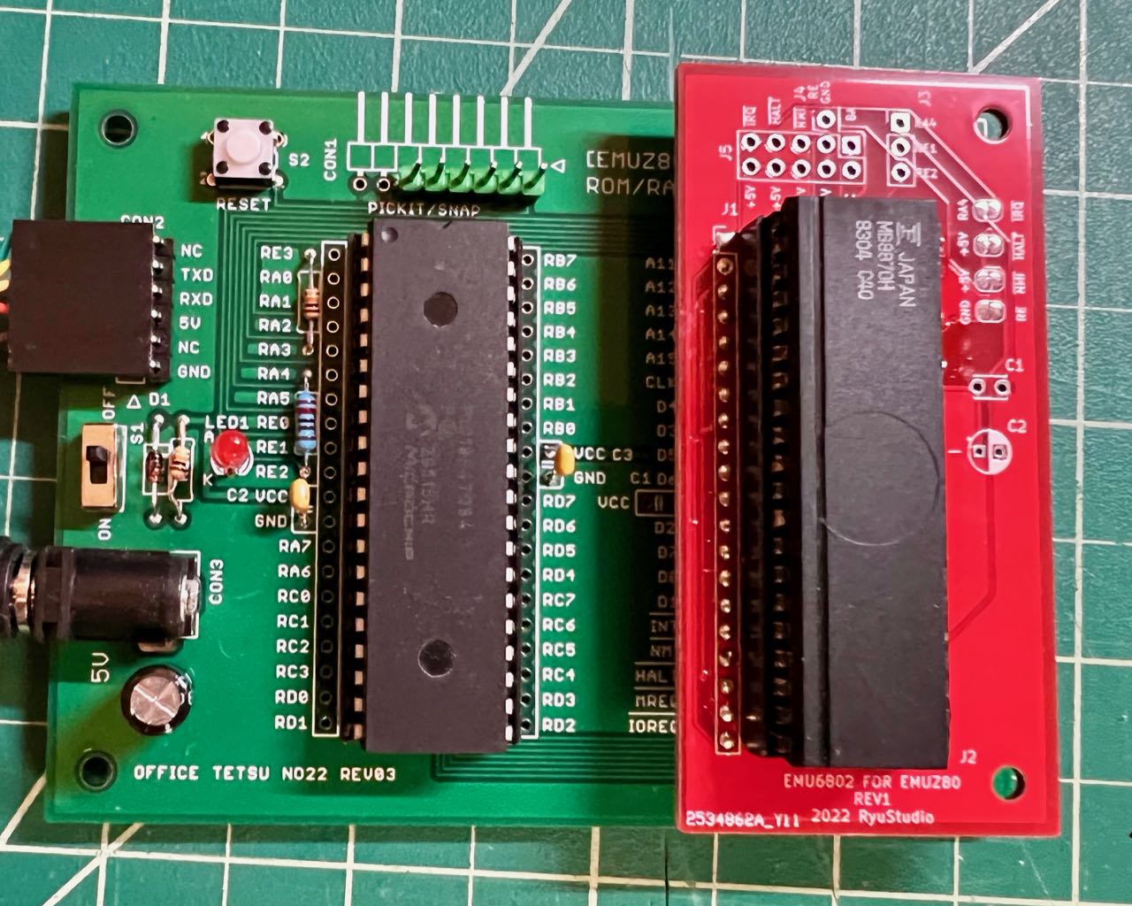
以下の部品が必要です。
上の画像では MC6802 互換の MB8870H を使用しています。
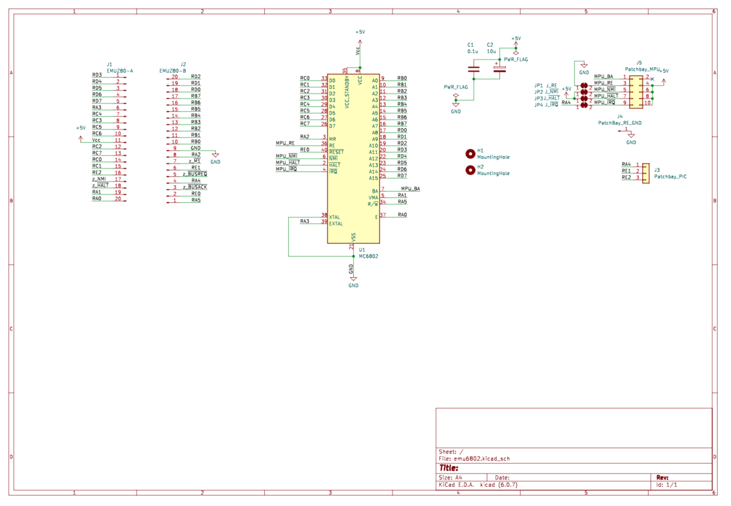
変換基板の配線を下の回路図に示します(PDF 版)。標準でデータバス、アドレスバス、制御信号、IRQ が配線されています。
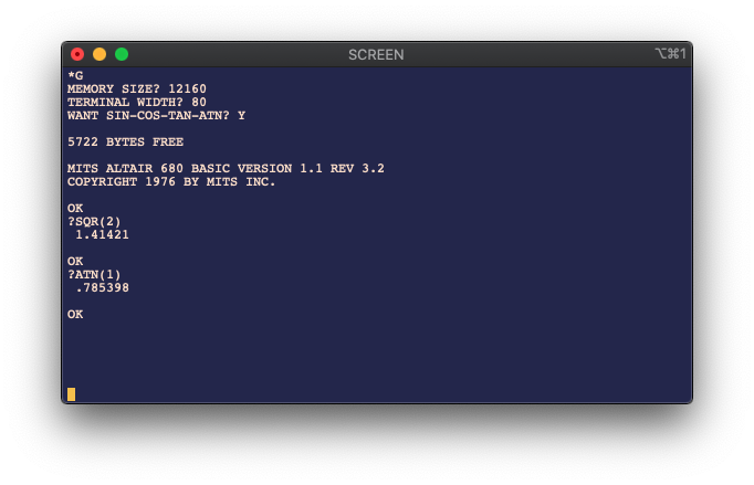
HEX ファイル emu6802.X.production.hex を PIC へ書き込みます(PIC18F47Q84 用です)。ソースコードは emu6802.X 以下を参照してください。プロジェクトは MPLAB X IDE で開きます。
EMUZ80 と同様に PIC が MPU バス信号を読み取って ROM、RAM、UART、タイマをエミュレートします。通常のハードウェアに比べてメモリ応答が遅くなるので、6802 の MR ピンを使ってシステムクロック E をストレッチしています。現状のコードでは、外部クロック入力 EXTAL に 2.3MHz を入力した場合に BASIC プログラムが最も高速に動作するようです。このとき 6802 のシステムクロック E は 387kHz 程度です。
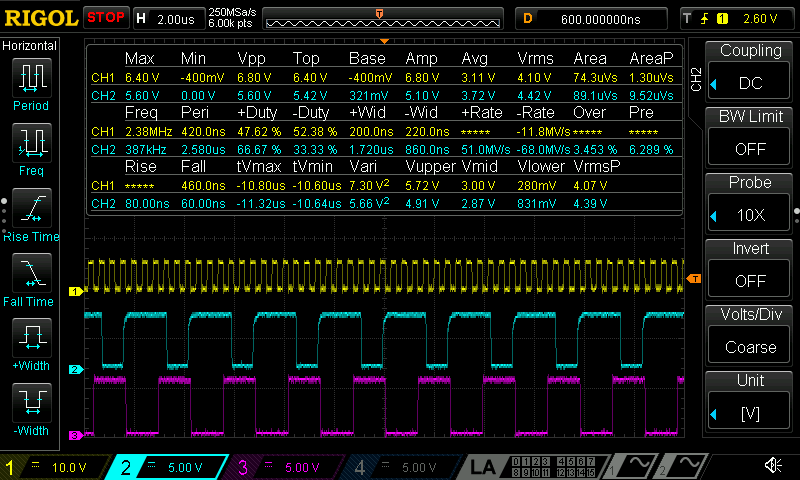
(Ch1: EXTAL, Ch1: E, Ch3: MR)
PIC タイマモジュール TU16A の出力が CLC の FF 回路を経由して 6802 の IRQ に接続されます。6802 メモリ空間の $A007 - $A00F で TU16A の設定レジスタにアクセスできます。アドレスとレジスタの対応は下表のとおりです。
| 6802 アドレス | PIC レジスタ名 |
|---|---|
| 0xa007 | TU16ACON0 |
| 0xa008 | TU16ACON1 |
| 0xa009 | TU16AHLT |
| 0xa00a | TU16APS |
| 0xa00b | TU16ATMRH / TU16ACRH |
| 0xa00c | TU16ATMRL / TU16ACRL |
| 0xa00d | TU16APRH |
| 0xa00e | TU16APRL |
| 0xa00f | TU16ACLK |
| 0xa01f | IRQ フラグリセット |
タイマ割り込みを応用した MC6802 時計表示プログラムが clock.a です。
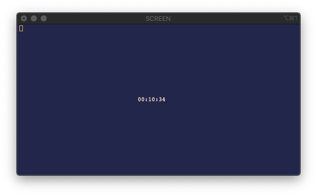
また PIC コードによって動く RTC がプログラムされており、RTC の時刻データを $B000 - $B003 で読み書きできるようにしてあります。$B010 への書き込みアクセスをしたタイミングで時刻がセットされます。この場合 IRQ 割り込みは不要です。これを利用した Basic 時計表示プログラムが clock.bas です。
なお PIC の内部発振は誤差 2% 程度なので、実用的な RTC としては精度が不十分です。
| Qty | Value | Footprint | References |
|---|---|---|---|
| 2 | MountingHole | MountingHole:MountingHole_3.2mm_M3 | H1, H2 |
| 1 | 0.1u | Capacitor_THT:C_Disc_D3.0mm_W2.0mm_P2.50mm | C1 |
| 1 | 10u | Capacitor_THT:CP_Radial_D4.0mm_P2.00mm | C2 |
| 1 | EMUZ80-A | myLibrary:PinHeader_1x20_P2.54mm_Narrow | J1 |
| 1 | EMUZ80-B | myLibrary:PinHeader_1x20_P2.54mm_Narrow | J2 |
| 1 | J_RE | Jumper:SolderJumper-2_P1.3mm_Bridged_RoundedPad1.0x1.5mm | JP1 |
| 1 | J_~{HALT} | Jumper:SolderJumper-2_P1.3mm_Bridged_RoundedPad1.0x1.5mm | JP3 |
| 1 | J_~{IRQ} | Jumper:SolderJumper-2_P1.3mm_Bridged_RoundedPad1.0x1.5mm | JP4 |
| 1 | J_~{NMI} | Jumper:SolderJumper-2_P1.3mm_Bridged_RoundedPad1.0x1.5mm | JP2 |
| 1 | MC6802 | Package_DIP:DIP-40_W15.24mm | U1 |
| 1 | PatchBay_RE_GND | Connector_PinHeader_2.54mm:PinHeader_1x01_P2.54mm_Vertical | J4 |
| 1 | Patchbay_MPU | Connector_PinHeader_2.54mm:PinHeader_2x05_P2.54mm_Vertical | J5 |
| 1 | Patchbay_PIC | Connector_PinHeader_2.54mm:PinHeader_1x03_P2.54mm_Vertical | J3 |
It measures 37 × 75 mm and has 2 copper layers, 1.6 mm thick.
14 parts. The full list of its parts is on this page, with links to each part's symbol and footprint where PCBKit's library has them.
From the ryu10/emu6802 repository on GitHub, at the commit this page was made from: the board is emu6802_conv.kicad6/emu6802/emu6802.kicad_pcb and its schematic emu6802_conv.kicad6/emu6802/emu6802.kicad_sch. PCBKit opens the board in the browser, with nothing to install.
Its repository states no licence, so its author keeps all rights: ask ryu10 before reusing the design.
google/mozc-devices
Circuit diagrams and firmware source code for Gboard DIY keyboards


hackclub/OnBoard
💡 Join 1,000 teenagers and make your first PCB with a $100 grant!


Twotoz/C5VRX
Ultra-minimal, zero-CPU 5.8 GHz analog FPV video receiver using ESP32-C5 Wi-Fi 6 PHY MODEM_DIAG, BitScrambler WBFM demodulation & resistor DAC CVBS

