2 layers50 × 35 mm

 rysiu2007/Simple-microphone-preamplifier
It is the upload of my microphone preamplifier project which i have made in 2024.
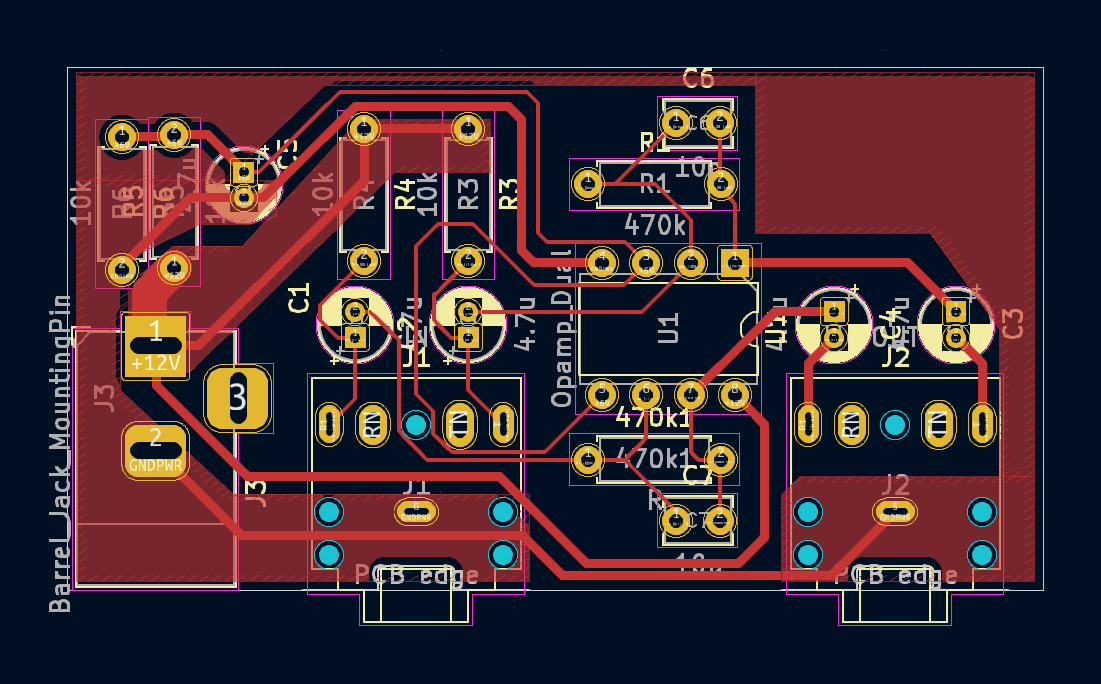
Microphone is an open-source printed circuit board by rysiu2007, from the rysiu2007/Simple-microphone-preamplifier repository on GitHub. It is a 2-layer board of 56 × 30 mm with 17 parts on 11 nets, routed with 101 tracks and 0 vias.
Its parts include 7 capacitors, 5 resistors, 3 connectors and 1 IC. It belongs with the audio and music boards of this library.
This repository contains the design and documentation for a high-gain microphone preamplifier utilizing the F4558 Dual Operational Amplifier. The circuit is optimized for low-noise amplification of small-signal audio inputs.
The design uses both halves of the F4558 (U1A and U1B) to provide dual-channel processing.
The gain for this specific inverting setup is defined by the input impedance of the microphone vs the feedback resistor ($R_f$):
$$V_{out} \approx -I_{in} \times R_f$$
The low-pass cutoff frequency ($f_c$) created by the feedback network is: $$f_c = \frac{1}{2\pi \times 470k\Omega \times 10pF} \approx 33.8 \text{ kHz}$$ This ensures the full audible spectrum is captured while filtering out unwanted RF interference.
| Qty | Value | Footprint | References |
|---|---|---|---|
| 5 | 4.7u | Capacitor_THT:CP_Radial_D4.0mm_P1.50mm | C1, C2, C3, C4, C5 |
| 4 | 10k | Resistor_THT:R_Axial_DIN0207_L6.3mm_D2.5mm_P7.62mm_Horizontal | R3, R4, R5, R6 |
| 2 | 10p | Capacitor_THT:C_Disc_D3.8mm_W2.6mm_P2.50mm | C6, C7 |
| 1 | 470k | Resistor_THT:R_Axial_DIN0207_L6.3mm_D2.5mm_P7.62mm_Horizontal | R1 |
| 1 | Barrel_Jack_MountingPin | Connector_BarrelJack:BarrelJack_Horizontal | J3 |
| 1 | IN | Connector_Audio:Jack_3.5mm_CUI_SJ1-3525N_Horizontal | J1 |
| 1 | OUT | Connector_Audio:Jack_3.5mm_CUI_SJ1-3525N_Horizontal | J2 |
| 1 | Opamp_Dual | Package_DIP:DIP-8_W7.62mm | U1 |
| 1 | R | Resistor_THT:R_Axial_DIN0207_L6.3mm_D2.5mm_P7.62mm_Horizontal | 470k1 |
It measures 56 × 30 mm and has 2 copper layers, 1.6 mm thick.
17 parts. The full list of its parts is on this page, with links to each part's symbol and footprint where PCBKit's library has them.
From the rysiu2007/Simple-microphone-preamplifier repository on GitHub, at the commit this page was made from: the board is Kicad/microphone.kicad_pcb and its schematic Kicad/microphone.kicad_sch. PCBKit opens the board in the browser, with nothing to install.
Its repository states no licence, so its author keeps all rights: ask rysiu2007 before reusing the design.


hoglet67/RGBtoHDMI
Bare-metal Raspberry Pi project that provides pixel-perfect sampling of Retro Computer RGB/YUV video and conversion to HDMI


hackclub/OnBoard
💡 Join 1,000 teenagers and make your first PCB with a $100 grant!

DDeGonge/OS-ARM
This arm is not industrial and it will not be fast, but that is not my goal. But it will hopefully be a very nice looking arm fully capable of 6dof motion, cheap enough to keep it accessable but capable enough to…

