2 layers370.8 × 298.5 mm
8 Bit Computer
The-Invent0r/8-bit-Computer-PCB
These are the KiCAD files for my 8-Bit Computer.
323 parts142

 ryomuk/emu8080on400425
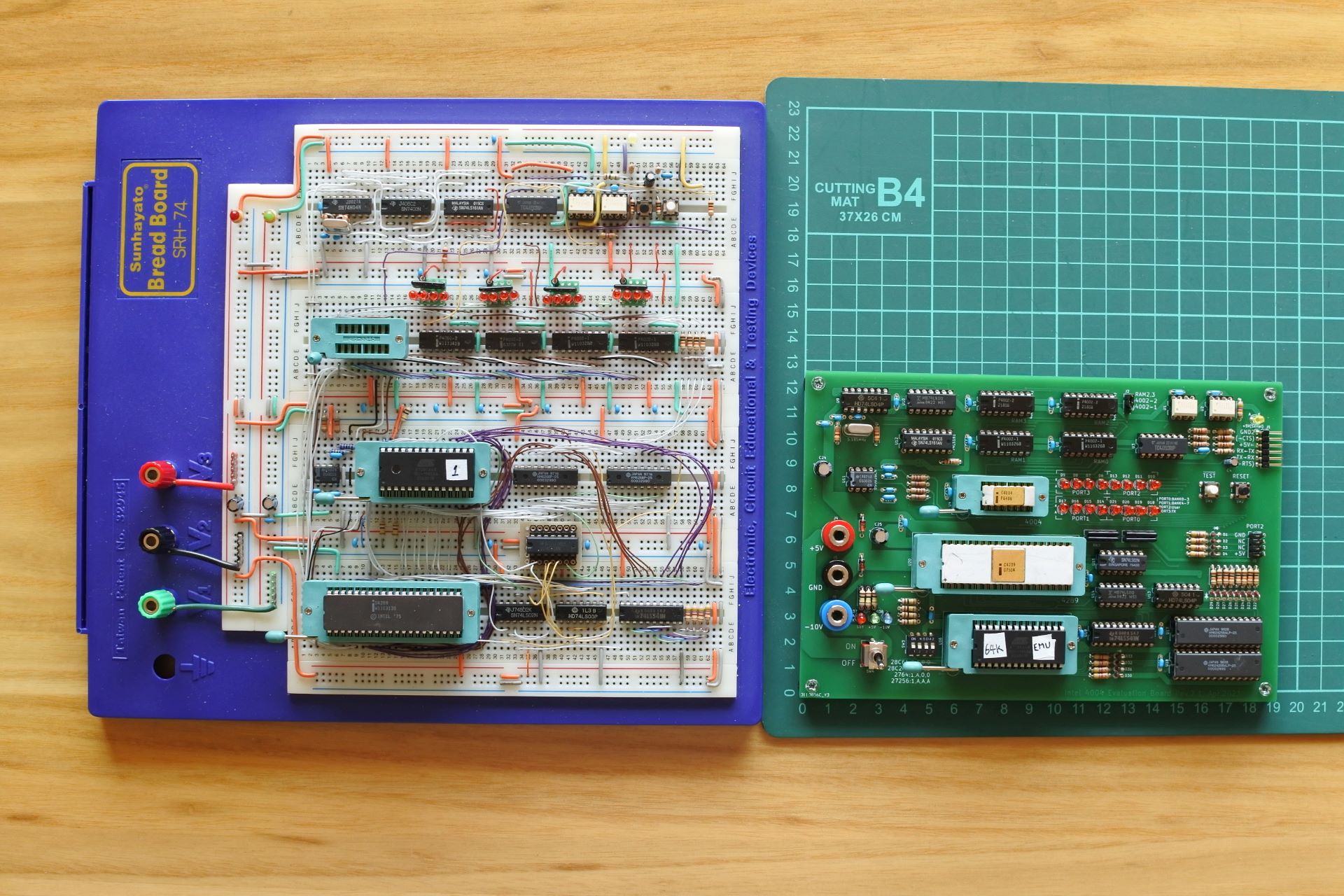
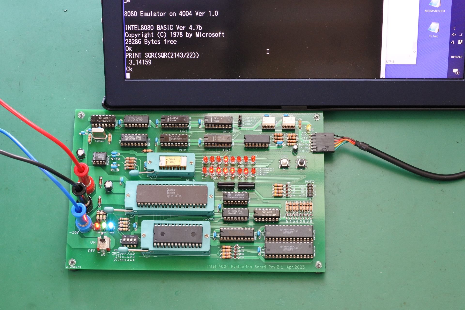
Intel 8080 Emulator on 4004 Evaluation Board
Test4004 is an open-source printed circuit board by ryomuk, from the ryomuk/emu8080on4004 repository on GitHub, published under the MIT licence. It is a 2-layer board of 190.5 × 127 mm with 140 parts on 169 nets, routed with 1,881 tracks and 146 vias.
It is built around the 74LS00SC, 74LS02PC and 74LS04PC, with the 74LS161DC among its other parts. Its parts include 38 resistors, 38 diodes, 25 capacitors, 20 ICs and 6 connectors. It belongs with the computers and single-board computers and retro computing and games boards of this library.


Intel 8080 Emulator on 4004 Evaluation Board
This document is written mostly in Japanese. If necessary, please use a translation service such as DeepL (I recommend this) or Google.
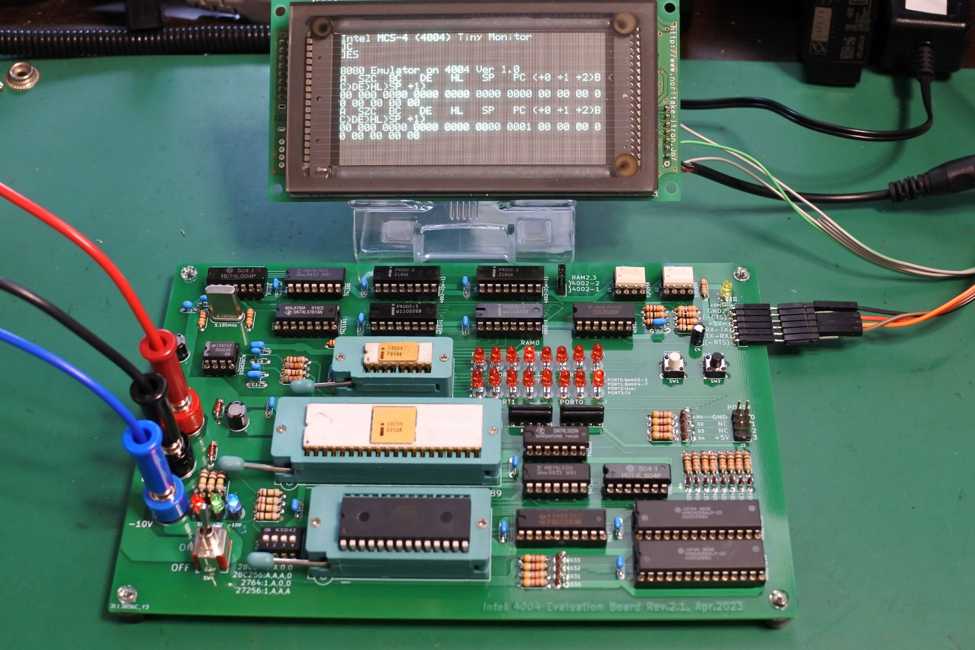
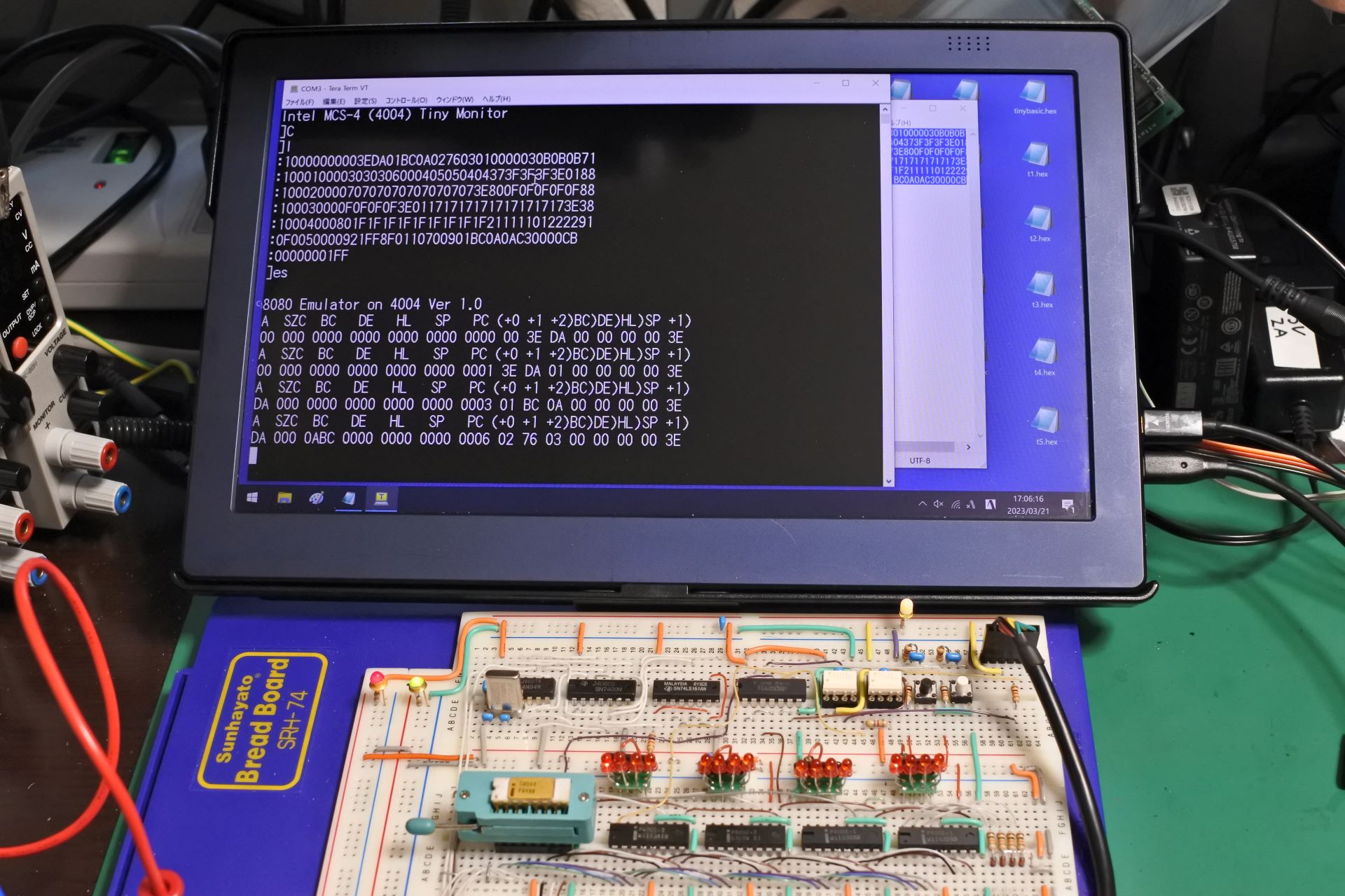
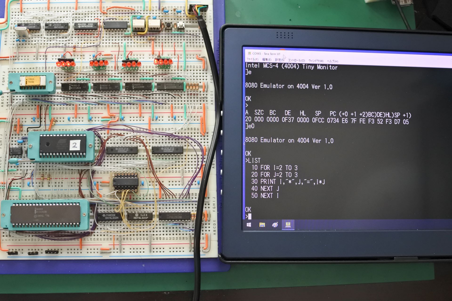
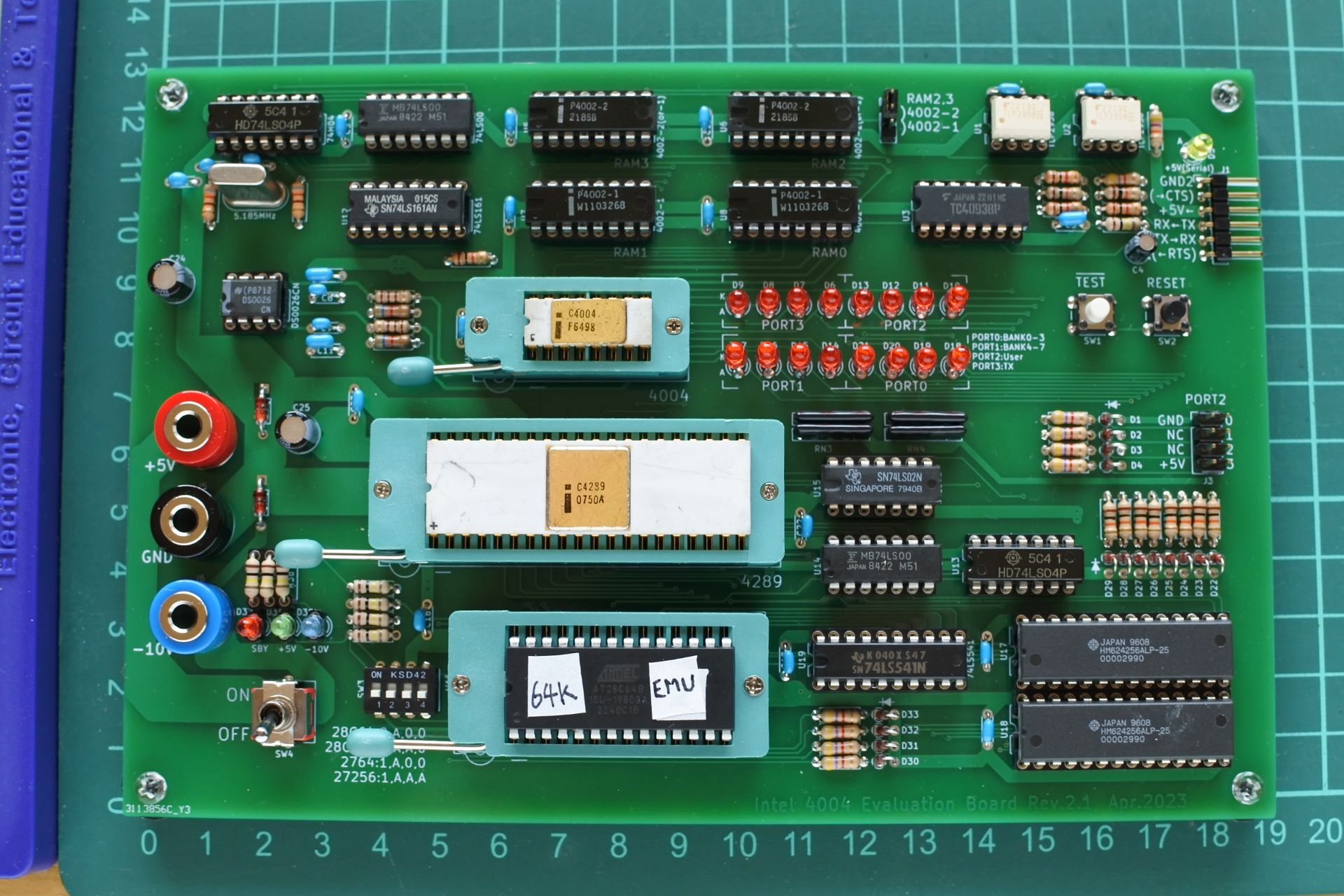
自作の4004実験用ボードと,その上で動作する8080エミュレータです.Palo Alot Tiny BASIC(4K整数型BASIC)や,Grant Searle's BASIC(8K浮動小数点BASIC)の8080移植版がほぼそのまま動くレベルの機能が実現できています.動作速度は8080実機の1/700程度です.
Youtubeで関連動画を公開しています.
関連する情報が書いてあるかも.
| Qty | Value | Footprint | References |
|---|---|---|---|
| 16 | 1N4148 | 000_MyFootprint:D_DO-35_SOD27_P2.54mm_Vertical_AnodeUp | D1, D2, D3, D4, D22, D23, D24, D25, D26, D27, D28, D29, D30, D31, D32, D33 |
| 16 | LED | 000_MyFootprint:LED_D3.0mm | D6, D7, D8, D9, D10, D11, D12, D13, D14, D15, D16, D17, D18, D19, D20, D21 |
| 15 | 0.1uF | 000_MyFootprint:C_Disc_D4.3mm_W1.9mm_P5.00mm | C1, C2, C5, C6, C13, C14, C15, C16, C17, C18, C19, C20, C21, C22, C23 |
| 10 | 10k | 000_MyFootprint:R_Axial_DIN0207_L6.3mm_D2.5mm_P7.62mm_Horizontal | R8, R10, R20, R21, R22, R23, R24, R25, R26, R27 |
| 9 | 4.7k | 000_MyFootprint:R_Axial_DIN0207_L6.3mm_D2.5mm_P7.62mm_Horizontal | R1, R2, R3, R4, R7, R32, R33, R34, R35 |
| 6 | 100k | 000_MyFootprint:R_Axial_DIN0207_L6.3mm_D2.5mm_P7.62mm_Horizontal | R12, R28, R29, R30, R31, R37 |
| 4 | 100k | 000_MyFootprint:R_Array_SIP5 | RN1, RN2, RN3, RN4 |
| 4 | 1k | 000_MyFootprint:R_Axial_DIN0207_L6.3mm_D2.5mm_P7.62mm_Horizontal | R6, R9, R11, R13 |
| 4 | MountingHole | 000_MyFootprint:MountingHole_3mm | H1, H2, H3, H4 |
| 3 | 0.01uF | 000_MyFootprint:C_Disc_D4.3mm_W1.9mm_P5.00mm | C8, C9, C10 |
| 3 | 1uF | 000_MyFootprint:C_Disc_D4.7mm_W2.5mm_P5.00mm | C3, C7, C11 |
| 2 | 110 | 000_MyFootprint:R_Axial_DIN0207_L6.3mm_D2.5mm_P7.62mm_Horizontal | R14, R15 |
| 2 | 4002-1 | 000_MyFootprint:DIP-16_W7.62mm | U7, U8 |
| 2 | 4002-2(or-1) | 000_MyFootprint:DIP-16_W7.62mm | U5, U6 |
| 2 | 470 | 000_MyFootprint:R_Axial_DIN0207_L6.3mm_D2.5mm_P7.62mm_Horizontal | R36, R38 |
| 2 | 47uF | 000_MyFootprint:CP_Radial_D6.3mm_P2.50mm | C24, C25 |
| 2 | 5.6k | 000_MyFootprint:R_Axial_DIN0207_L6.3mm_D2.5mm_P7.62mm_Horizontal | R18, R19 |
| 2 | 74LS00 | 000_MyFootprint:DIP-14_W7.62mm | U10, U14 |
| 2 | 820 | 000_MyFootprint:R_Axial_DIN0207_L6.3mm_D2.5mm_P7.62mm_Horizontal | R16, R17 |
| 2 | HM624256 | 000_MyFootprint:DIP-28_W10.16mm | U17, U18 |
| 2 | TLP2958 | 000_MyFootprint:DIP-8_W7.62mm | U1, U2 |
| 1 | +5V | 000_MyFootprint:Banana_Jack_1Pin | J4 |
| 1 | -10V | 000_MyFootprint:Banana_Jack_1Pin | J6 |
| 1 | 10uF | 000_MyFootprint:CP_Radial_D4.0mm_P1.50mm | C4 |
| 1 | 28C64B | 000_MyFootprint:DIP_Socket-28_W11.9_W12.7_W15.24_W17.78_W18.5_3M_228-1277-00-0602J | U16 |
| 1 | 4004_CPU | 000_MyFootprint:DIP_Socket-16_W4.3_W5.08_W7.62_W10.16_W10.9_3M_216-3340-00-0602J | U4 |
| 1 | 4093B | 000_MyFootprint:DIP-14_W7.62mm | U3 |
| 1 | 4289_MEMORY_IF | 000_MyFootprint:DIP_Socket-40_W11.9_W12.7_W15.24_W17.78_W18.5_3M_240-1280-00-0602J | U20 |
| 1 | 47k | 000_MyFootprint:R_Axial_DIN0207_L6.3mm_D2.5mm_P7.62mm_Horizontal | R5 |
| 1 | 5.185MHz | 000_MyFootprint:Crystal_HC49-U_Vertical | Y1 |
| 1 | 50pF | 000_MyFootprint:C_Disc_D4.3mm_W1.9mm_P5.00mm | C12 |
| 1 | 74H04 | 000_MyFootprint:DIP-14_W7.62mm | U9 |
| 1 | 74LS02 | 000_MyFootprint:DIP-14_W7.62mm | U15 |
| 1 | 74LS04 | 000_MyFootprint:DIP-14_W7.62mm | U13 |
| 1 | 74LS161 | 000_MyFootprint:DIP-16_W7.62mm | U12 |
| 1 | 74LS541 | 000_MyFootprint:DIP-20_W7.62mm | U19 |
| 1 | DS0026CN | 000_MyFootprint:DIP-8_W7.62mm | U11 |
| 1 | GND | 000_MyFootprint:Banana_Jack_1Pin | J5 |
| 1 | PORT2 | 000_MyFootprint:PinHeader_2x04_P2.54mm_Vertical | J3 |
| 1 | Pin Header 3P | 000_MyFootprint:PinHeader_1x03_P2.54mm_Vertical | J2 |
| 1 | RED | 000_MyFootprint:LED_D3.0mm | D37 |
| 1 | RESET | 000_MyFootprint:SW_PUSH_6mm_H4.3mm | SW2 |
| 1 | SW_DIP_x04 | 000_MyFootprint:SW_DIP_SPSTx04_Slide_6.7x11.72mm_W7.62mm_P2.54mm_LowProfile | SW3 |
| 1 | SW_DPDT | 000_MyFootprint:SW_DPDT_Toggle_with_mount | SW4 |
| 1 | TLG101 | 000_MyFootprint:LED_D3.0mm | D38 |
| 1 | TLR101 | 000_MyFootprint:LED_D3.0mm | D34 |
| 1 | UART(TTL) | 000_MyFootprint:PinHeader_1x06_P2.54mm_Horizontal | J1 |
| 1 | YELLOW | 000_MyFootprint:LED_D3.0mm | D5 |
| 1 | Zener12V | 000_MyFootprint:D_DO-35_SOD27_P7.62mm_Horizontal | D36 |
| 1 | Zener6.2V | 000_MyFootprint:D_DO-35_SOD27_P7.62mm_Horizontal | D35 |
| 1 | ~{TEST} | 000_MyFootprint:SW_PUSH_6mm_H4.3mm | SW1 |
The-Invent0r/8-bit-Computer-PCB
These are the KiCAD files for my 8-Bit Computer.

btb/80ColumnCard
An Apple II 80-Column Card. Based on the Videx Videoterm


rraider/Seminarkurs2021
Entwicklung eines turingvollständigen, primitiven Microcontroller in der Software Digital


misterblack1/zenith_zt1
Information gathered on the Zenith ZT-1 / ZT-10 / ZT-11 and ZTX/ZT-x-A variants


It measures 190.5 × 127 mm and has 2 copper layers, 1.6 mm thick.
140 parts, built around the 74LS00SC, 74LS02PC, 74LS04PC and 74LS161DC. The full list of its parts is on this page, with links to each part's symbol and footprint where PCBKit's library has them.
From the ryomuk/emu8080on4004 repository on GitHub, at the commit this page was made from: the board is hardware/rev2.1/test4004.kicad_pcb and its schematic hardware/rev2.1/ClockGen.kicad_sch. PCBKit opens the board in the browser, with nothing to install.
Its repository publishes it under the MIT licence: you may reuse it on that licence's terms (keep the author's notice, and for a copyleft licence share your changes alike).