2 layers50 × 35 mm
 Ryeece/Temperature-Warning-System1
Embedded temperature monitoring and warning system using an Arduino Mega2560, DHT11, 16x2 LCD, and custom KiCad shield PCB
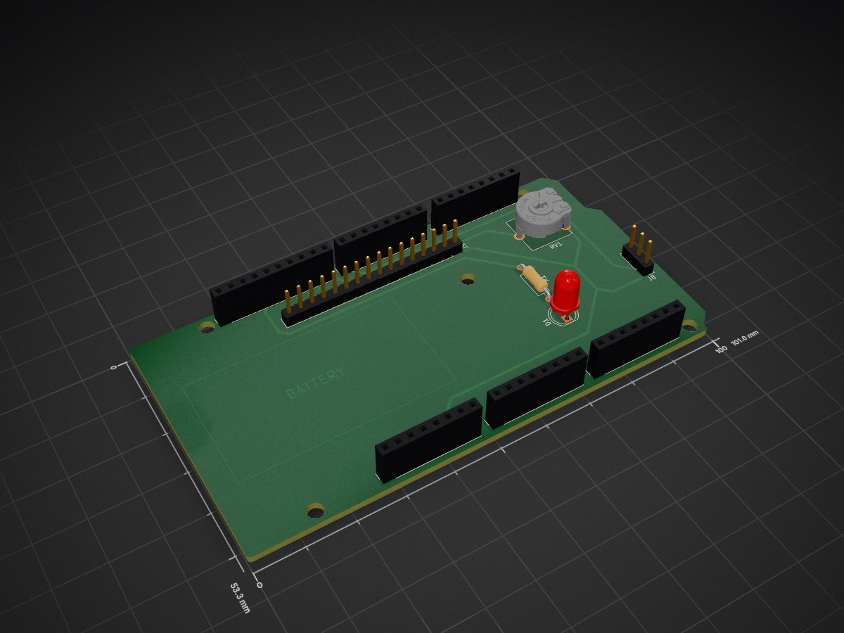
PCB Arduino shield for temperature sensor project is an open-source printed circuit board by Ryeece, from the Ryeece/Temperature-Warning-System repository on GitHub. It is a 2-layer board of 101.6 × 53.3 mm with 17 parts on 52 nets, routed with 45 tracks and 0 vias.
Its parts include 8 connectors, 1 resistor and 1 diode. It belongs with the sensors and measurement and lEDs and displays boards of this library.
Embedded temperature monitoring and warning system using an Arduino Mega 2560, DHT11, 16×2 LCD, and custom KiCad shield PCB
Using the Arduino Mega I measured the temperature with a DHT11 sensor and had the live temperature reading displayed on the 16×2 LCD. When the set temperature threshold was exceeded a warning LED turns on with a warning message on the 16×2 LCD. For sensor faults the warning LED turns on with a check sensor message on the 16×2 LCD. Finally a custom Mega shield PCB was designed in KiCad.
First the DHT11 takes the temperature reading, then it sends the data to the Mega and the Mega processes the reading using the uploaded code and displays the temperature on the LCD. If the temperature threshold is exceeded the warning LED turns on and a warning message is displayed on the LCD. Finally the function isnan() is used to detect an invalid sensor reading which activates the warning LED and error message on the LCD.
The system was first built and tested on a breadboard before being transferred into the custom Arduino Mega shield PCB design.
The temperature threshold was temporarily set to 29.8°C so the high-temperature warning could be tested at room temperature.
The system was initially tested on a breadboard to verify the temperature monitoring, warning LED, LCD messages and sensor fault detection before transferring the circuit to the custom PCB.
The manufactured PCB was then assembled and connected to the Arduino Mega 2560 to verify that the completed hardware operated correctly.
| Test | Expected Result | Result |
|---|---|---|
| Temperature below threshold | LED off and normal-temperature message displayed on the LCD | Pass |
| Temperature above threshold | LED on and high-temperature warning message displayed on the LCD | Pass |
| DHT11 signal disconnected | Warning LED on and sensor error message displayed on the LCD | Pass |
| Battery-powered operation | System operates without a laptop connection | Pass |
| Assembled PCB functionality | All components operate correctly through the custom PCB | Pass |
To test the isnan() fault handling, I deliberately disconnected the DHT11 signal. The Arduino detected the invalid sensor reading, activated the warning LED and displayed an error message on the LCD.
After soldering the components and headers onto the manufactured PCB, the shield was connected to the Arduino Mega 2560.
The system operated successfully during its initial testing, with the LCD displaying live temperature readings and the warning LED responding to the programmed conditions.
The normal-temperature, high-temperature warning and sensor fault states were successfully tested using the assembled PCB.
The completed system was also tested using a standalone 9V battery connected to the Arduino's power input, confirming that it could operate without a computer connection.
No changes to the PCB design were required for the system to function. However, a possible intermittent solder connection was identified as an area for further inspection.
The PCB was designed as an Arduino Mega shield so it could plug directly into the Mega.
KiCad schematic:
KiCad PCB layout:
3D view of the PCB Mega shield:
The Mega-template header footprints mainly establish the correct physical positions. In place of the female headers, male headers will be soldered underneath the physical PCB to allow connection to the Mega 2560, and female headers will be soldered on top for removable connections for the DHT11 and LCD.
After completing the PCB design in KiCad, I generated the Gerber and drill files required for manufacturing. These files were uploaded to JLCPCB, where I ordered the custom two-layer PCB.
Once the manufactured boards arrived, I assembled the circuit by soldering the components and pin headers onto the PCB using the soldering facilities at university.
The completed PCB was then connected to the Arduino Mega 2560 and powered using a 9V battery through the Arduino's barrel jack.
During initial testing, I encountered a minor connectivity issue, potentially caused by a solder joint. However, the PCB operated successfully without requiring any modifications to the original design.
This was my first experience taking a PCB design through the complete process of manufacturing, physical assembly and functional testing.
1. Manufactured PCB before assembly
2. Assembled PCB
3. PCB underside and solder joints
4. Completed and operational system
| Problem | Cause | Fix |
|---|---|---|
| External LED did not light | Both LED legs were connected to the same breadboard node | Repositioned the LED so each leg was connected to a different node |
| LCD displayed dark blocks instead of text | D7 was connected incorrectly | Corrected the LCD wiring so D7 connected to the correct LCD pin |
| Invalid DHT11 reading | Sensor communication failed when the signal was disconnected | Added isnan() fault detection, an LCD error message and warning LED activation |
| KiCad ERC/DRC warnings | Unused and duplicated connections in the Arduino Mega template | Used No Connect flags, PWR_FLAGs and intentional exclusions where appropriate |
The temperature warning system has been successfully developed, manufactured, assembled and tested.
After completing the circuit design and programming, I designed a custom Arduino Mega shield PCB using KiCad. The PCB was manufactured by JLCPCB, and I soldered all the components myself using the facilities at university.
Following assembly, the system operated successfully without requiring any PCB design modifications. A minor connectivity issue was encountered, potentially caused by a solder joint, but the system was able to function correctly.
The completed system successfully:
Measures and displays live temperature readings on a 16×2 LCD.
Detects temperatures exceeding the programmed threshold and displays a high-temperature warning.
Detects sensor faults and displays an error message.
Operates independently using a 9V battery connected to the Arduino Mega.
This project allowed me to develop practical skills in electronic circuit design, microcontroller programming, PCB design, soldering, troubleshooting and hardware testing. It was particularly rewarding to see a PCB I had independently designed operate successfully after manufacturing and assembly.
A temperature-controlled fan could be added, using PWM (Pulse Width Modulation) to automatically adjust the fan speed based on the measured temperature. This would allow the system to actively regulate temperature rather than simply provide a warning.
User-adjustable buttons could be implemented to allow the temperature warning threshold to be changed without modifying and uploading the Arduino code.
The power supply could be improved by replacing the 9V battery with a more efficient rechargeable power source, allowing the system to operate independently for longer periods.
A protective enclosure could also be designed to house the Arduino, custom PCB and other components, making the completed system more compact and suitable for practical use. Eventually, the Arduino Mega can be replaced with a microcontroller mounted directly on the PCB.
| Qty | Value | Footprint | References |
|---|---|---|---|
| 6 | MountingHole_3.2mm | Arduino_MountingHole:MountingHole_3.2mm | MH1, MH2, MH3, MH4, MH5, MH6 |
| 2 | Analog | Connector_PinSocket_2.54mm:PinSocket_1x08_P2.54mm_Vertical | J3, J5 |
| 1 | 10K | Potentiometer_THT:Potentiometer_ACP_CA9-V10_Vertical | RV1 |
| 1 | 220R | Resistor_THT:R_Axial_DIN0207_L6.3mm_D2.5mm_P10.16mm_Horizontal | R1 |
| 1 | Communication | Connector_PinSocket_2.54mm:PinSocket_1x08_P2.54mm_Vertical | J6 |
| 1 | Conn_01x03_Pin | Connector_PinHeader_2.54mm:PinHeader_1x03_P2.54mm_Vertical | J8 |
| 1 | Conn_01x16_Pin | Connector_PinHeader_2.54mm:PinHeader_1x16_P2.54mm_Vertical | J9 |
| 1 | LED | LED_THT:LED_D5.0mm | D1 |
| 1 | PWM | Connector_PinSocket_2.54mm:PinSocket_1x08_P2.54mm_Vertical | J4 |
| 1 | PWM | Connector_PinSocket_2.54mm:PinSocket_1x10_P2.54mm_Vertical | J2 |
| 1 | Power | Connector_PinSocket_2.54mm:PinSocket_1x08_P2.54mm_Vertical | J1 |
It measures 101.6 × 53.3 mm and has 2 copper layers, 1.6 mm thick.
17 parts. The full list of its parts is on this page, with links to each part's symbol and footprint where PCBKit's library has them.
From the Ryeece/Temperature-Warning-System repository on GitHub, at the commit this page was made from: the board is pcb/PCB Arduino shield for temperature sensor project.kicad_pcb and its schematic pcb/PCB Arduino shield for temperature sensor project.kicad_sch. PCBKit opens the board in the browser, with nothing to install.
Its repository states no licence, so its author keeps all rights: ask Ryeece before reusing the design.


hoglet67/RGBtoHDMI
Bare-metal Raspberry Pi project that provides pixel-perfect sampling of Retro Computer RGB/YUV video and conversion to HDMI


hackclub/OnBoard
💡 Join 1,000 teenagers and make your first PCB with a $100 grant!

DDeGonge/OS-ARM
This arm is not industrial and it will not be fast, but that is not my goal. But it will hopefully be a very nice looking arm fully capable of 6dof motion, cheap enough to keep it accessable but capable enough to…

