2 layers43.9 × 27.7 mm

 ryanhsiehrh/QUADRUPED-ROBOT-OLED
Quadruped robot powered by an Arduino Pro Micro (ATmega32U4). Operates on 5V power, utilizing 12 servo motors for inverse kinematics and an animated OLED display face through Software I2C.
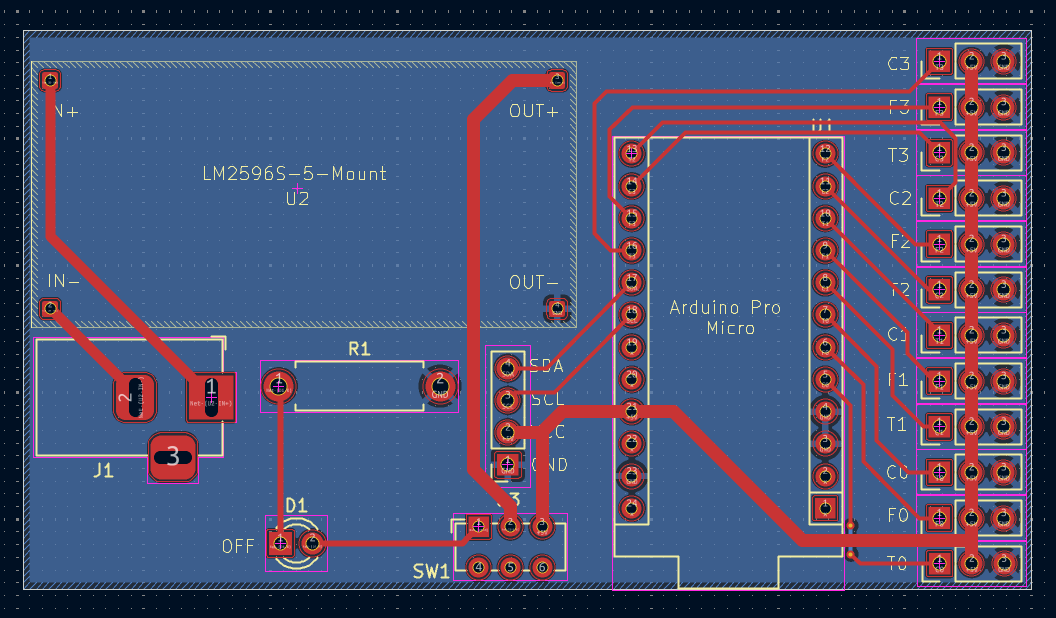
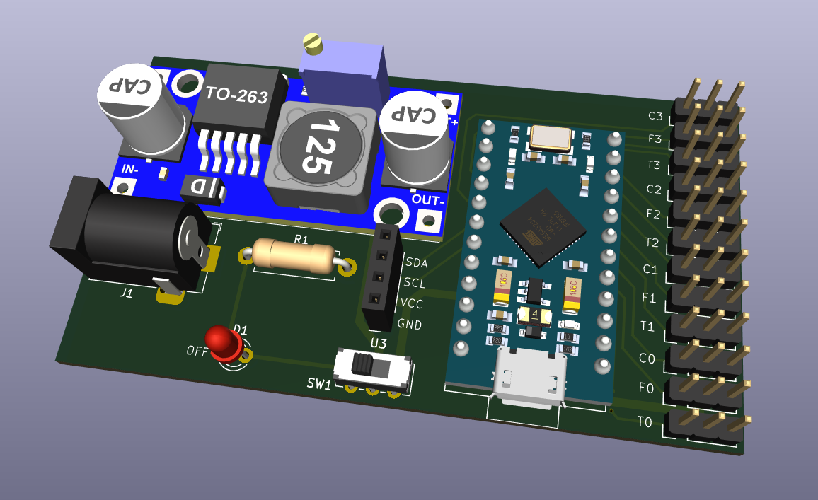
PRO MICRO SCHEMATIC is an open-source printed circuit board by ryanhsiehrh, from the ryanhsiehrh/QUADRUPED-ROBOT-OLED repository on GitHub. It is a 2-layer board of 79.5 × 44 mm with 19 parts on 27 nets, routed with 75 tracks and 2 vias.
Its parts include 3 ICs, 1 resistor, 1 diode, 1 connector and 1 switch. It belongs with the robots and motor control and lEDs and displays boards and the AVR (ATmega, ATtiny) boards of this library.
Quadruped robot powered by an Arduino Pro Micro (ATmega32U4). Operates on 5V power, utilizing 12 servo motors for inverse kinematics and an animated OLED display face through Software I2C.
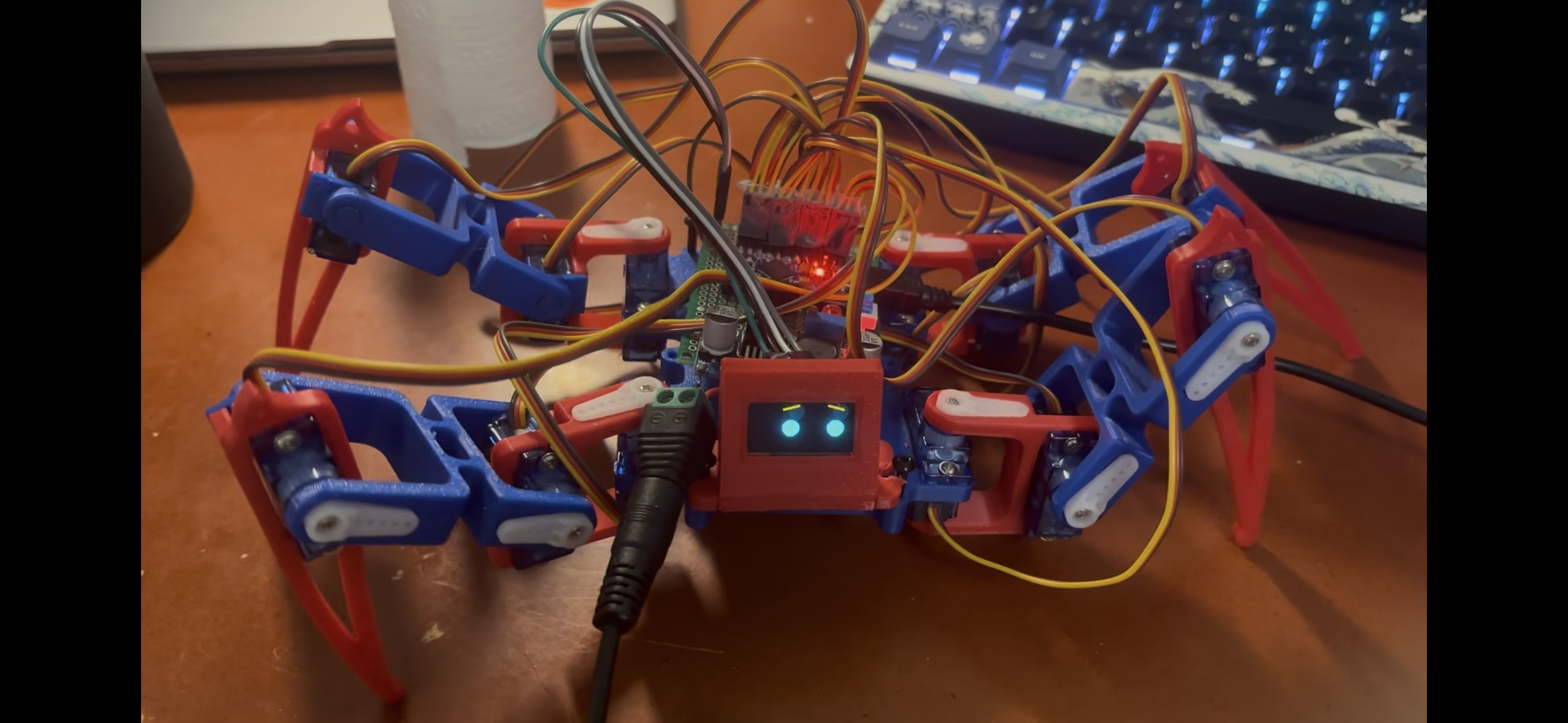
A0 (SDA) and A1 (SCL).FlexiTimer2 to keep servo updates running smoothly in the background.| Component | Function | Arduino Pro Micro Pin |
|---|---|---|
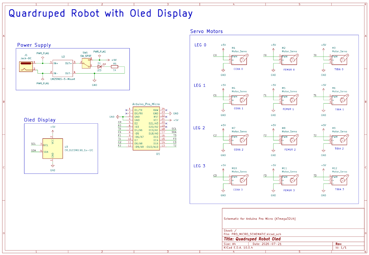
| OLED Display | SDA (Data) | A0 (Software I2C) |
| OLED Display | SCL (Clock) | A1 (Software I2C) |
| Leg 0 (Back Left) | Coxa / Femur / Tibia | Pins 2, 3, 4 |
| Leg 1 (Front Left) | Coxa / Femur / Tibia | Pins 5, 6, 7 |
| Leg 2 (Back Right) | Coxa / Femur / Tibia | Pins 8, 9, 10 |
| Leg 3 (Front Right) | Coxa / Femur / Tibia | Pins 16, 14, 15 |
Schematic:
PCB:
Set your Serial Monitor to 9600 Baud and Newline. Type any of the following commands:
w 0 1 – Stand Up (wakes up face display)w 0 0 – Sit Down (closes eyes on display)w 1 x – Walk Forward x stepsw 2 x – Walk Backward x stepsw 3 x – Turn Right x stepsw 4 x – Turn Left x stepsw 5 x – Hand Shake emote (x times)w 6 x – Hand Wave emote (x times)w 7 x – Side-to-Side body sway (x times)w 8 x – Bounce body emote (x times)w 9 x – Up and Down stretch (x times)Install these via the Arduino Library Manager or online:
U8g2 (for operating OLED screen)FlexiTimer2 (for 50Hz timer interrupts)SerialCommand (for parsing serial input strings)Servo (standard servo motor library)The chassis and leg components are based on Regis Hsu's Spider Robot Design on Thingiverse.
servo_90.ino to set all 12 servos to their $90^\circ$ midpoint.QUADRUPED-ROBOT-OLED.ino, select Arduino Leonardo, and flash the sketch.w 0 1 to stand the robot up!Watch the Quadruped Robot video here!
| Qty | Value | Footprint | References |
|---|---|---|---|
| 12 | Motor_Servo | Connector_PinHeader_2.54mm:PinHeader_1x03_P2.54mm_Vertical | M1, M2, M3, M4, M5, M6, M7, M8, M9, M10, M11, M12 |
| 1 | 1k | Resistor_THT:R_Axial_DIN0411_L9.9mm_D3.6mm_P12.70mm_Horizontal | R1 |
| 1 | Arduino_Pro_Micro | Arduino:Sparkfun_Pro_Micro | U1 |
| 1 | ER_OLEDM0.96_1x-I2C | Connector_PinSocket_2.54mm:PinSocket_1x04_P2.54mm_Vertical | U3 |
| 1 | Jack-DC | Connector_BarrelJack:BarrelJack_Horizontal | J1 |
| 1 | LED | LED_THT:LED_D3.0mm | D1 |
| 1 | LM2596S-5-Mount | Library:LM2596S-5-Mount | U2 |
| 1 | SW_SPDT | Button_Switch_THT:SW_E-Switch_EG1271_SPDT | SW1 |

hackclub/OnBoard
💡 Join 1,000 teenagers and make your first PCB with a $100 grant!

polpo/picogus
Emulation of ISA sound cards and CD-ROM on Raspberry Pi Pico (GUS, SB/Adlib, MPU-401, Tandy, CMS, Panasonic CD-ROM) with USB mouse/joystick support


nkitanov/iaq_board
IAQ Board is a DIY (Do-It-Yourself) device for measuring internal air quality


Ardumower/ardumower
Develop an open source robotic lawn mower (HW+SW reference platform)

zmaker/arduino_cookbook
gli sketch del nuovo progetto Arduino Cookbook e dei video di YouTube
It measures 79.5 × 44 mm and has 2 copper layers, 1.6 mm thick.
19 parts. The full list of its parts is on this page, with links to each part's symbol and footprint where PCBKit's library has them.
From the ryanhsiehrh/QUADRUPED-ROBOT-OLED repository on GitHub, at the commit this page was made from: the board is Kicad Files/PRO_MICRO_SCHEMATIC.kicad_pcb and its schematic Kicad Files/PRO_MICRO_SCHEMATIC.kicad_sch. PCBKit opens the board in the browser, with nothing to install.
Its repository states no licence, so its author keeps all rights: ask ryanhsiehrh before reusing the design.