2 layers45 × 45 mm
 rx178nwj/-ParallelLevelShifter
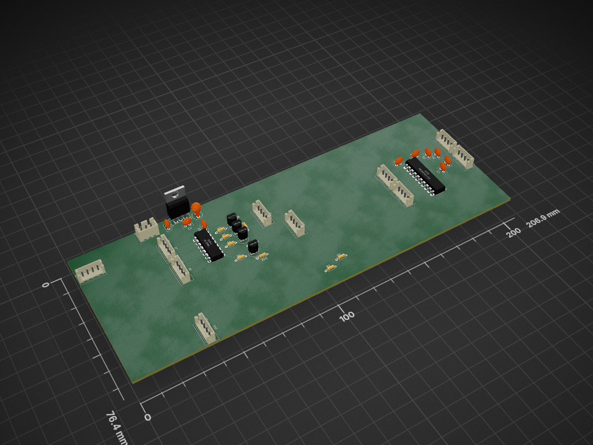
Prototype levelshifter is an open-source printed circuit board by rx178nwj, from the rx178nwj/-ParallelLevelShifter repository on GitHub. It is a 2-layer board with 38 parts on 41 nets, routed with 25 tracks and 0 vias.
It is built around the 74HC14, L7805 and 2SC1815. Its parts include 11 connectors, 10 capacitors, 10 resistors, 4 transistors and 3 ICs. It belongs with the interfaces and adapters boards of this library.


8ch 双方向ロジックレベル変換基板(KiCad プロジェクト)
複数のブレイクアウトピンヘッダから同一の8bitバスへ並列にアクセスできる、8チャンネル双方向レベルシフタ基板です。バッテリー給電で 5V / 3.3V を自前生成し、両電源とも配布用ヘッダごとにジャンパでON/OFFできます。
| 参照符号 | 部品 | 役割 |
|---|---|---|
| U1 | 74LVC8T245 (TSSOP-24) | 8bit 双方向レベルシフタ本体 |
| U2 | NCP1117-5.0 (SOT-223) | +5V LDO レギュレータ |
| U3 | NCP1117-3.3 (SOT-223) | +3.3V LDO レギュレータ |
| J1〜J4 | Conn_01x04 | A側 信号ヘッダ(各2ch + GND + VCC) |
| J5〜J8 | Conn_01x04 | B側 信号ヘッダ(各2ch + GND + VCC) |
| J9 | Conn_01x02 | バッテリー / DC電源入力 |
| JP1〜JP4 | ジャンパ 2P | 各ヘッダへの +3.3V 給電 ON/OFF |
| JP5, JP6 | ジャンパ 2P | U1 の DIR ピン論理レベル選択(3.3V / GND) |
| R1〜R50 | 抵抗 10kΩ | 各信号ラインのプル抵抗 |
| R34 | 抵抗 1kΩ | LED 電流制限抵抗 |
| C1〜C14 | コンデンサ | 電源デカップリング |
| D1, D2 | LED | 電源インジケータ |
| H1〜H4 | 取り付け穴 | 基板固定用 |
抵抗値・ネット構成は KiCad スキーマティックの自動解析によるものです。実際に使用する際は KiCad で回路図を開き、各ネットを必ず確認してください。
.
├── schmatics/                      # 現行の KiCad プロジェクト(最新版)
│   ├── PararellLevelShifter.kicad_pro
│   ├── PararellLevelShifter.kicad_sch   # 回路図
│   ├── PararellLevelShifter.kicad_pcb   # 基板データ
│   ├── PararellLevelShifter-backups/    # KiCad 自動バックアップ
│   └── 20221116Gaber/                   # 製造用 Gerber / ドリルデータ一式
└── old/
    └── prototype_levelshifter/     # 初期プロトタイプ版 KiCad プロジェクト
schmatics/20221116Gaber/ には基板製造用の Gerber ファイル一式(*.gbr)とドリルファイル(*.drl)、ジョブファイル(*.gbrjob)が含まれています。old/ フォルダには開発初期のプロトタイプ回路(試作段階の別プロジェクト)が保管されています。現行仕様は schmatics/ 配下を参照してください。20211123 / PCB フォーマット互換)schmatics/PararellLevelShifter.kicad_pro を開くschmatics/20221116Gaber/ 内の Gerber / ドリルデータをそのまま基板製造業者へ入稿、または PCB エディタから再生成未定(ライセンスを追加する場合は本セクションを更新してください)
| Qty | Value | Footprint | References |
|---|---|---|---|
| 10 | Conn_01x04_Male | Connector_JST:JST_XA_B04B-XASK-1_1x04_P2.50mm_Vertical | J1, J2, J3, J4, J6, J7, J8, J9, J10, J11 |
| 9 | C_Small | Capacitor_THT:C_Disc_D5.0mm_W2.5mm_P2.50mm | C1, C2, C3, C4, C5, C6, C7, C9, C10 |
| 4 | 2SC1815 | Package_TO_SOT_THT:TO-92_Inline | Q2, Q3, Q5, Q6 |
| 4 | 4.7k | Resistor_THT:R_Axial_DIN0204_L3.6mm_D1.6mm_P5.08mm_Horizontal | R7, R8, R9, R10 |
| 4 | 470 | Resistor_THT:R_Axial_DIN0204_L3.6mm_D1.6mm_P5.08mm_Horizontal | R3, R4, R5, R6 |
| 2 | 1k | Resistor_THT:R_Axial_DIN0204_L3.6mm_D1.6mm_P5.08mm_Horizontal | R1, R2 |
| 1 | 74HC14 | Package_DIP:DIP-14_W7.62mm | U3 |
| 1 | AKI-FXMA108 | Package_DIP:DIP-20_W7.62mm_LongPads | U1 |
| 1 | C_Polarized_Small | Capacitor_THT:CP_Radial_Tantal_D5.0mm_P2.50mm | C8 |
| 1 | Conn_01x03_Male | Connector_JST:JST_XA_B03B-XASK-1_1x03_P2.50mm_Vertical | J5 |
| 1 | L7805 | Package_TO_SOT_THT:TO-220-3_Vertical | U2 |
38 parts, built around the 74HC14, L7805 and 2SC1815. The full list of its parts is on this page, with links to each part's symbol and footprint where PCBKit's library has them.
From the rx178nwj/-ParallelLevelShifter repository on GitHub, at the commit this page was made from: the board is old/prototype_levelshifter/prototype_levelshifter.kicad_pcb and its schematic old/prototype_levelshifter/prototype_levelshifter.kicad_sch. PCBKit opens the board in the browser, with nothing to install.
Its repository states no licence, so its author keeps all rights: ask rx178nwj before reusing the design.


kazushinjo/Shonan_Lite-androidPhone-SSBFM
Shonan_Lite for Android phone + SSB/FM transceiver tab (port of Langstone-V2 by G4EML)


Zinjpq/Egg_incubator_project
Major exercise of pulse engineering subject

transistorfet/computie
A collection of 68k computer projects, including a unix-like operating system written in C that runs on them


and3rson/pk88
Single-board computer based on KM1810VM88 CPU (Ukrainian clone of Intel 8088).