2 layers103 × 30.5 mm

 RustyRailways/RustyRailways9
Rust and Godot Based Autonomous Lego Train System
Switch PCB ESP01 is an open-source printed circuit board by RustyRailways, from the RustyRailways/RustyRailways repository on GitHub, published under the MIT licence. It is a 2-layer board of 20 × 54 mm with 9 parts on 10 nets, routed with 60 tracks and 2 vias.
Its parts include 5 connectors, 2 resistors and 2 transistors. It belongs with the ESP8266 boards of this library.

Group Project by lucaSartore (Sartore Luca), cattai-lorenzo (Cattai Lorenzo), MrLakige (Callegari Michele), Technorico (Peruzzo Federico) for Embedded Software for The Internet of Things - 145996 taught by professor Kasim Sinan Yildirim at University of Trento, DISI Department.
This is a system that automates the motion of Lego trains and rail switches. You can tell the system in which station you want a train to go (either using an HTTP request or using our GUI), and the system will figure out the best way to achieve the goal, even moving trains that are on your way if necessary.
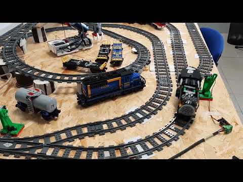
The system is implemented using 5 different components:
The Master: This is the component that does all the calculations to find the optimal path, and then controls the trains and the switches, you can learn more about the master hereThe Client: (Godot based client to create the train track and control/monitor the train system), you can learn more about the client hereThe Map: The map is a support data structure (a modified graph in particular) used by the master, you can learn more about the master hereThe Common Infrastructure: The common infrastructure defines some basic messages that all components need to communicate with each other, as well as the IPs and the hardware abstraction layer traits, you can learn more about the master hereThe Trains: You can learn more about the code that manages the trains hereThe Switches: You can learn more about the code that manages the switches hereHere you can find a quick list of the things you need to do, to try our project yourself.
The current implementation of the master runs on a Linux system (e.g. Raspberry Pi with Raspberry Pi OS) so to run it, you just need to install the regular rust toolchain. Given that we used a Hardware Abstraction Layer (HAL) to implement the master, with a bit more work, it can be executed on something smaller (like an ESP-32), if you are interested in this you can check out the train toolchain installation down below.
The train code is written in embedded rust, with the embedded-hal and embedded-svc crates. To install the software needed to build for our target (The ESP-32) you can follow the tutorial here.
To compile the switch code you can follow this tutorial we have written.
See Client README.md.
Files to print the switch mechanism are located here You can find a 3D printing tutorial here.
To build the switch PCB you can follow this tutorial we have written
FabLab UniTn for the space, tools and part of the materials used
| Qty | Value | Footprint | References |
|---|---|---|---|
| 3 | Conn_01x02 | RustyRailways_Lib:01x02_TerminalBlock | J1-3.3V1, J2-5V1, J3-GND1 |
| 2 | 10k | Resistor_THT:R_Axial_DIN0204_L3.6mm_D1.6mm_P2.54mm_Vertical | R1, R2 |
| 2 | Q_NMOS_SGD | Connector_PinHeader_2.54mm:PinHeader_1x03_P2.54mm_Vertical | Q1, Q2 |
| 1 | Conn_01x03 | Connector_PinHeader_2.54mm:PinHeader_1x03_P2.54mm_Vertical | J4-Servo1 |
| 1 | Conn_02x04_Odd_Even | RustyRailways_Lib:ESP01 | J0-ESP01S1 |
It measures 20 × 54 mm and has 2 copper layers, 1.6 mm thick.
9 parts. The full list of its parts is on this page, with links to each part's symbol and footprint where PCBKit's library has them.
From the RustyRailways/RustyRailways repository on GitHub, at the commit this page was made from: the board is switch/hardware/Switch_PCB/KiCAD/Switch_PCB_ESP01/Switch_PCB_ESP01.kicad_pcb and its schematic switch/hardware/Switch_PCB/KiCAD/Switch_PCB_ESP01/Switch_PCB_ESP01.kicad_sch. PCBKit opens the board in the browser, with nothing to install.
Its repository publishes it under the MIT licence: you may reuse it on that licence's terms (keep the author's notice, and for a copyleft licence share your changes alike).


FrameworkComputer/ExpansionCards
Reference designs and documentation to create Expansion Cards for the Framework Laptop

VoronDesign/Voron-Hardware
Cool Hardware designed by the Voron Design group

hackclub/OnBoard
💡 Join 1,000 teenagers and make your first PCB with a $100 grant!


adamws/kicad-kbplacer
KiCad plugin for automatic keyboard's key placement and routing